20
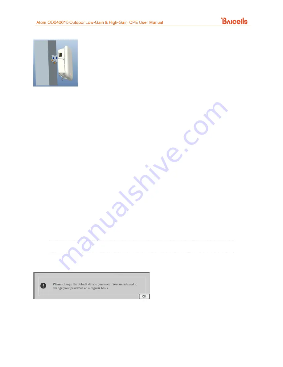
Figure 24: Attach CPE
b6) Proceed to
section 7
11.
Power on the CPE and wait a few minutes while the CPE boots up. Per Table 3, check that the LED
indicators are lighting as expected.
7 Basic Configuration
Reference:
The CPE comes preloaded with a Graphical User Interface (GUI) to configure the device. The GUI screens
for CAT4 and CAT6/7/15 CPEs look different, though both contain many of the same types of settings. This
manual covers both GUIs and points out where there are differences.
The basic configuration settings allow you to get the CPE up and running, i.e., connected to the Internet,
to verify operation. Other features as well as more in-depth information about the CPE GUIs are covered
in the document referenced above.
7.1 Log in
With your computer connected through Ethernet to the CPE:
1.
NOTE: If the address does not open the GUI, try
. These were used
for older generation CPEs.
2.
Upon first login, you may be prompted to change your password (Figure 25).
Figure 25: First Login
When you click on
OK
, you will be taken to the
System
>
Account
window (Figure 26). Enter a password
using 5 to 16 characters (upper/lower case letters, numbers, and special characters). For CAT4, click on
SAVE &
APPLY
. For CAT6/7/15, click
Apply.
For CAT6/7/15, in the
System > Account
window you can change the lockout time, i.e., if there is
no activity on the CPE for this amount of time, users will be logged off. The default is 300 seconds
(five minutes), and the maximum is 65535 seconds (~18 hrs). Click on
Apply
to save.


