background image


11


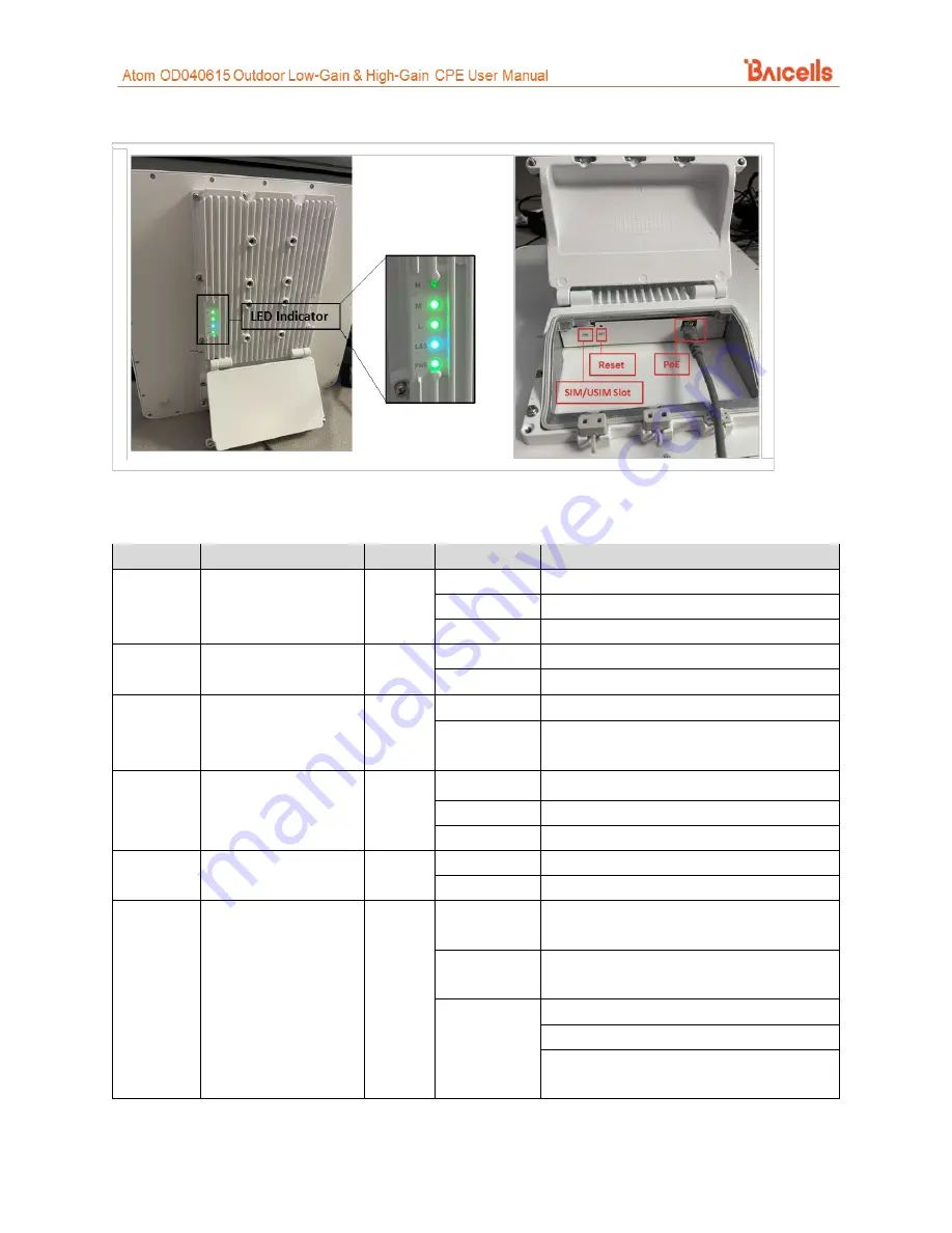
Figure 5: Atom OD15 High-Gain LEDs & Interfaces 


Table 3: LED Descriptions 

LEDs vary by model – not all models will have all of the LEDs listed below.   

Identity 

Description 

Color 

Status 

Description 

MIU 

Yellow 

Off 

Reserved for future use 

Steady On 

Reserved for future use 

Blinking 

Reserved. for future use 

LTE 

LTE network status 

Blue 

Off 

The CPE is not connected to the network   

Steady On 

The CPE is connected to the LTE network 

SIM/USIM  SIM/USIM card status 

Yellow 

Steady On 

The USIM card is functioning normally 

Blinking 

The USIM card is not inserted or is not 
functioning normally 

LAN 

100 or 1000 Mbps 
Local Area Network 
Ethernet status 

Yellow 

Off 

No Ethernet connection established 

Steady On 

Ethernet connection is normal 

Blinking 

Data is transmitting 

PWR 

Power status 

Yellow 

Off 

No power supply to the CPE 

Steady On 

Power to the CPE is on 

LTE Signal 

1, 2, 3, 4, or 5 bars to 
indicate wireless 
connection status. The 
more bars, the 
stronger the signal 
between the CPE and a 
network cell (eNB). 

Green 

All Off 

The signal is too weak for the CPE to 
connect to the network 

Steady On 

Bars will light steadily according to signal 
strength   

Blinking 

The CPE is scanning the network 
The CPE is authenticating with the network 
The CPE is getting an IP address from the 
network 


Summary of Contents for Atom OD040615

Page 1: ...Atom OD040615 Outdoor Low Gain High Gain CPE User Manual BaiCE_AP_2 4 7_NA BaiCE_BG_1 6 20 January 2022 Version 1 12...

Page 2: ...Gain CPE model EG7035E Atom OD06L Outdoor CAT6 7 Low Gain CPE model EG7010C Atom OD06H Outdoor CAT6 7 High Gain CPE model EG7010A Atom OD06 LX Outdoor CAT6 Low Gain CPE model EG8013L Atom OD15 OD15 E...

Page 3: ...0 V1 7 New branding Chris Culver Sharon Redfoot 18 Sep 2019 13 Sep 2019 V1 6 V1 5 SME comments Updated for naming convention change BaiCE_AP_2 2 1_NA CAT4 and BCE_MD 1 0 1 B036SP28 NA CAT6 7 15 and ge...

Page 4: ...G 29 7 5 CONFIGURE CONNECTION MODE CONNECTION SETTINGS 30 7 6 CONFIGURE SCAN MODE CELL SELECTION 31 7 5 1 Overview 31 7 5 2 CAT4 32 7 5 3 CAT6 7 15 34 7 7 CONFIGURE APN MANAGEMENT EDIT APN PROFILE 36...

Page 5: ...Figure 11 Low Gain CPE Ground Screw 15 Figure 12 High Gain CPE Ground Screw and Ground Row 16 Figure 13 Power Adaptor 16 Figure 14 Rubber Band 17 Figure 15 Bracket 17 Figure 16 Attach CPE 17 Figure 1...

Page 6: ...ure 39 Dedicated EARFCN CAT6 7 15 35 Figure 40 PCI Lock CAT6 7 15 35 Figure 41 PCI only Lock CAT6 7 15 36 Figure 42 APN Management Edit APN Profile 37 Figure 43 Device Info 39 Figure 44 LTE Status 40...

Page 7: ...es preloaded with a Graphical User Interface GUI application to configure the device The GUI menus and screens for CAT4 and CAT6 7 15 look different though both contain many of the same types of setti...

Page 8: ...e primary components that you should receive with the Baicells outdoor CPEs Table 1 Parts Item Qty Picture Atom OD0406 Low Gain or High Gain unit 1 Atom OD15 unit 1 Power Cable 1 PoE Power Adaptor 1 A...

Page 9: ...orter than 330 ft 100 m Ground Wire 6 AGW 16 mm2 yellow green wire 4 Description The Baicells Atom outdoor low gain and high gain CPE models are powerful standards based devices designed to connect se...

Page 10: ...nal status and to check cables On the low gain CPE the LEDs are on the side of the unit and the connection interfaces are on the bottom of the unit On the high gain CPE both the LEDs and the interface...

Page 11: ...d is not inserted or is not functioning normally LAN 100 or 1000 Mbps Local Area Network Ethernet status Yellow Off No Ethernet connection established Steady On Ethernet connection is normal Blinking...

Page 12: ...eption If you are installing the outdoor CPE with a Baicells SNAP PoE Router please refer to the SNAP PoE Router Installation Guide There will be some installation differences At the time of this publ...

Page 13: ...ernet cable The Ethernet cable will run between the outdoor CPE and the inside of the facility where it will connect to the PoE adaptor and LAN Cable length will vary by location 4 Connect one end of...

Page 14: ...om OD15 5 Close the waterproof cover and tighten the screws 6 Prepare the 6 AWG 16 mm2 yellow green ground wire and follow the ground steps below Once the unit is fully installed make sure the ground...

Page 15: ...om Low Gain CPE Connect the ground cable to the ground screw Figure 11 NOTE The location of the ground screw varies by model Figure 11 Low Gain CPE Ground Screw b Atom High Gain CPE Connect the ground...

Page 16: ...attention to the power adaptor interface directions noted on the adaptor itself The LED indicators should light up when the unit is powered on Figure 13 Power Adaptor 8 Mount the CPE If you are insta...

Page 17: ...et over the band using the hoop Figure 15 Figure 15 Bracket a3 Attach the CPE to the bracket and tighten the screw Figure 16 Figure 16 Attach CPE a4 The CPE is now ready for installation at its final...

Page 18: ...eady for installation at its final outside location Proceed to section 7 10 Wall installation a Low Gain CPE a1 Slip the bracket off of the Atom unit and fit it on the wall to mark the drilling locati...

Page 19: ...up to the wall and mark the drilling locations Figure 23 Figure 23 Mark Holes for Drilling b2 Drill two 0 5 in 12 mm diameter and 3 1 in 80 mm depth holes at the marked locations on the wall b3 Tap th...

Page 20: ...CPE GUIs are covered in the document referenced above 7 1 Log in With your computer connected through Ethernet to the CPE 1 Open a Web browser and enter http 192 168 150 1 NOTE If the address does no...

Page 21: ...w Figure 27 enter the default user name admin and your password If you were not prompted to change the password upon initial login enter the default password also admin Click on LOGIN This will take y...

Page 22: ...IP address it means the CPE is in the process of establishing a connection Give it a few moments to finish its connection process and then check if the status is Connected Otherwise make sure the CPE...

Page 23: ...etwork Address Translation NAT or Bridge mode depending on your network topology NAT allows multiple hosts on a private network to access the Internet using a single public IP address Bridge mode disa...

Page 24: ...24 Figure 29 WAN Settings CAT4...

Page 25: ...ar for each operation mode 2 In the Profile List you will see up to eight APNs You must have at least one APN configured for the CPE TR 069 connection to the Baicells CloudCore Local OMC Operations Ma...

Page 26: ...26 Figure 30 WAN Settings CAT6 7 15 1 of 2...

Page 27: ...e hosts on a private network to access the Internet using a single public IP address Bridge The WAN port addresses will bridge to the LAN port and the LAN port will work in trunking mode If you select...

Page 28: ...ter the secondary DNS server s IP address Tunnel Mode CAT6 7 15 Only VPN Type L2TP or GRE NAT Support Enable Disable NAT on the VPN Default Route VPN or WAN Host name Optional enter the default route...

Page 29: ...Basic Settings pane click on the checkbox next to Enable to initiate Wifidog and enter the AP code and the Authentication Server Address If you don t want to create a whitelist or configure advanced...

Page 30: ...work you want to connect to each time 1 In the CAT4 GUI go to LTE Connection Mode and in the CAT6 7 15 GUI go to LTE Connection Settings to choose Automatic CAT4 Always On CAT6 7 15 or Manual Figure 3...

Page 31: ...connection to the LTE network The setting determines which frequencies the CPE s routine scan of available frequencies will cover Scanning is a process of tuning to specific frequencies and using a s...

Page 32: ...ck You can lock the CPE to a designated PCI or PCI range If you wish to leave the scan mode as Full Band you do not need to make any configuration changes for the mode The procedures for configuring t...

Page 33: ...ode select Cell Lock from the pull down menu 2 Click on ADD LIST to open the Cell Lock Setting pane 3 Select the Band number and enter the Earfcn and PCI number combination 4 Click on ADD Then click S...

Page 34: ...ing are the procedures for configuring Dedicated EARFCN PCI Lock and PCI only Lock on a CAT6 7 15 CPE Dedicated EARFCN Figure 38 1 For Scan Mode select Dedicated EARFCN from the pull down menu 2 Ident...

Page 35: ...ull down menu and click on Apply 2 In the PCI Setting pane select the Band number 3 For Type choose either EARFCN or Frequency and enter the associated number 4 Enter a PCI ID number 0 503 and click o...

Page 36: ...Internet In a Baicells system where the operator uses the Baicells CloudCore to connect to the backhaul the APN establishes one connection between the CPE and the EPC Evolved Packet Core via the eNB...

Page 37: ...In CAT4 enter the Maximum Transmission Unit MTU packet size that can be sent on this APN The range is 576 1500 bytes NOTE For CAT6 7 15 the MTU setting is in the LTE MTU menu and the range is 1280 150...

Page 38: ...ective Isotropic Radiated Power EIRP and Power Spectral Density PSD Under these guidelines the Baicells outdoor CPEs are classified as Category B The CPE Configuration Guide describes basic configurat...

Page 39: ...n such as model number hardware version software version etc Figure 42 Device Info 8 2 LTE Status The LTE Status section of the Status Overview window offers USIM card status IMSI and IMEI numbers as...

Page 40: ...on 7 6 As you scroll down the Status Overview window the APN Status section it is called Internet Status in CAT6 7 15 displays each configured APN gateway Figure 45 At least one APN APN1 is by default...

Page 41: ...tatus part of the Overview window displays the Local Area Network MAC address IP address and Netmask Figure 46 If you are having issues connecting to the LAN WAN check this window for the basic IP net...

Page 42: ...Status Overview window to the Devices List Figure 47 If too many users are accessing the Internet through the CPE at the same time on a CAT6 7 15 CPE you may consider limiting the IP address range and...

Reviews: