background image

BA-440 DualBeam Barcode Reader Quickstart Guide Ver 5

8. Route Wiring to Terminals

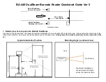
Take wiring and route it to the terminal block as shown in this Illustration. 
Take care not to leave wires too long or put stress on the reader circuit 
boards and components.

9. Make Wiring Connections

Strip insulation and connect wiring to Decoder at the terminal block in the upper left hand corner.

GND IN 

POWER INPUT

 Ground or common input from 24VDC source

+24V 

POWER INPUT 

Positive input from 24VDC source

RELAY OUTPUT

, Gate, normally open (NO)

GdRead-

RELAY OUTPUT

, Gate, normally open (NO)

Aux In+ 

INPUT

 for Vehicle presence trigger

Aux In- 

INPUT

 for Vehicle presence trigger

RELAY OUTPUT

, Auxiliary, normally open (NO)

AuxOut-

RELAY OUTPUT

, Auxiliary, normally open (NO)

GND

GROUND 

from reader power input

Data1 

WIEGAND 1 

(Data 1) communication output to access control system

Data0 

WIEGAND 0 

(Data 0) communication output to access control system

Comm 

GROUND 

or Common signal connection to access control system

Recommended wire for power is 18 AWG copper (minimum) for runs up to 200’. 

Summary of Contents for BA-440 DualBeam

Page 1: ...not matter which side of the road it is mounted on as long as the vehicle decals are on the same side Always place the reader and decals on the same side of the car Typical Installation Position Mount...

Page 2: ...ver with 1 8 blade Wire stripper 4 Unpack Reader Remove Decoder Module box Hardware and Accessories box and Reader Enclosure from the shipping box Take Reader Enclosure from bag and flip upside down R...

Page 3: ...6 Seal wiring port in Baseplate Once the wiring is run up the mounting post and out through the hole in the Baseplate you can use the 4 putty roll from the hardware bag to seal the opening in the bas...

Page 4: ...he gold polygon This gold polygon should face the road with the terminal block for connections at the rear of the Baseplate Use the four 5 16 nylock nuts on the threaded studs to secure the decoder mo...

Page 5: ...DC source 24V POWER INPUT Positive input from 24VDC source GdRead RELAY OUTPUT Gate normally open NO GdRead RELAY OUTPUT Gate normally open NO Aux In INPUT for Vehicle presence trigger Aux In INPUT fo...

Page 6: ...ly 5Vdc present on the Data0 and Data1 terminals If the voltage is present communications should operate fine 11 Convert to Direct Wiegand connection if Optoisolated connection does not function Direc...

Page 7: ...n a short beep from the BA 440 and data transmission out both the serial port and Wiegand port Decal should read out to at least 6 out from the reader NOTE You must wait at least 1 second after a read...

Page 8: ...ck the voltage on Data 0 and Data 1 to see if there is 5 VDC present If no voltage is found or if voltage is less than 3 Vdc Wiegand messages cannot be sent Be sure the access system is connected and...

Page 9: ...the test circuit is live for 10 minutes after you turn the test switch ON then it will go into hibernation This is to preserve battery life if the technician forgets to turn the test circuit off To re...

Page 10: ...be secured using all 6 flanged nuts for a good seal IMPORTANT Thread all 6 nuts finger tight first then tighten only 1 4 to 1 2 turn more on each nut CAUTION The seal on the reader Hood and hardware m...

Reviews: