Baelz Automatic BA 111 Operating Instructions Manual Download Page 13

BA_1

11_00_DEF_MJ_0419

13 | 

23

W. Baelz & Sohn GmbH & Co.

 · Koepffstrasse 5 · 74076 Heilbronn · Germany · 

www.baelz.de             Seite | Page  

Straight-Tube Heat Exchanger baelz 111 / baelz 112

5.3  During operation

If vibration, noise, reduced power or other disturbances occur during operation, please refer to the 

Troubleshooting table on page 16 and contact Baelz customer service if necessary. 


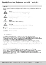
Observe the following instructions for safe commissioning!

Beware


12.  Open the condensate manual control and isolating valve very slowly to put the steam heat transfer 

station into operation: First open the manual control valve by only one turn. After 15 minutes, check 

the resulting temperature rise. If the maximum supply temperature (secondary output, 04) is already 

exceeded, the condensate control valve is too large. Turn the manual control valve back accordingly. If 

the supply temperature is not reached, open the manual control valve by one more turn. Wait another 

15 minutes and repeat the temperature check and, if necessary, correct the hand wheel position. Now 

secure the manual control valve so that it cannot be unintentionally misadjusted.

13.  Since the temperature provides only limited information about the heat output, the correct condensate 

discharge rate must in certain cases be set on the manual control valve using a condensate meter. The 

approx. condensate discharge capacity in l/min, which must flow at nominal capacity, is obtained by 

dividing the heat output in kcal/h by the numerical value 33000. If the capacity is given in kW, it must be 

divided by the numerical value 38 in order to obtain the approx. condensate quantity in l/min. Particularly 

advantageous is when the condensate control valve contains a built-in flow limiter. It can be easily 

adjusted to the maximum flow rate. 

14.  Now you can switch on the automatic operation. The automatic condensate control valve is controlled by 

the controller by means of Open and Close pulses depending on the power consumption. Observe the 

system for a few more hours and note the pressure and temperature values. Check the safety devices 

for correct function by simulating controls as they may occur during operation.


After 1-2 hours of operation, tighten the screws of the seals!

Caution

15.  It is imperative to tighten the screw connections of all seals gradually and evenly after 1-2 hours of operation. 

See also chapter 6.4. This measure is necessary because seals change under the influence of heat. If 

the retightening is not carried out in time, the seals may be damaged and the device may leak. This can 

result in seals having to be replaced and, under certain circumstances, sealing surfaces having to be 

reworked. 


In new systems, strainers must be cleaned after the first few days.

Caution

16. 

Clean the strainers to remove debris that may have been flushed from the system's recently put into 

service pipes and fittings.

17.  Security valves are usually set for the pressure value ordered. Corrections must be made at the 

manufacturer's factory. Installations subject to inspection must be inspected after completion by the body 

designated in accordance with the PED. The certificate of a factory construction and water pressure test 

must be submitted.

Summary of Contents for BA 111

Page 1: ...4076 Heilbronn Germany www baelz de Seite Page BA_111_00_DEF_MJ_0419 Operating Instructions BA 111 112 Straight Tube Heat Exchanger baelz 111 baelz 112 Technical specifications subject to change witho...

Page 2: ...hnical data 7 2 4 Pressure equipment directive 7 2 5 Water quality 7 3 TRANSPORT AND STORAGE 8 4 ASSEMBLY 9 4 1 Assembly instructions 9 4 2 Measuring equipment 9 4 3 Arrangement of the control system...

Page 3: ...ube Heat Exchanger baelz 111 baelz 112 8 TROUBLESHOOTING 16 9 DIMENSIONAL DRAWING ASSEMBLY PLAN SYSTEM DIAGRAMS EXAMPLES 18 9 1 Tables baelz 111 112 with tube length 1500 mm 19 9 2 baelz 111 112 with...

Page 4: ...The technical data of the heat exchanger and the permissible values for operating pressure and operating temperature apply as specified on the name plate Any use for tasks deviating from the above me...

Page 5: ...o the information on the name plate of the heat exchanger baelz 111 baelz 112 1 5 During operation Safe operation is only possible if transport storage assembly operation and maintenance is carried ou...

Page 6: ...t reglation using condensate backup The water to be heated flows through the tubes while steam is fed through the housing The tube bundle is firmly welded in Removable head covers allow the inspection...

Page 7: ...VA plated or stainless steel Head Steel Steel stove enamelled Stainless steel Shell Steel Parts in contact with the fluid 1 4571 Insulation Mineral wool with galvanized sheet metal jacket 50 80 mm Ho...

Page 8: ...Beware Wear the required personal and other protective equipment Avoid shocks blows vibrations and the like on the heat exchanger Store the heat exchanger and if necessary the complete station in a d...

Page 9: ...the heat exchanger bear in mind that later removal may be necessary e g for maintenance Provide sufficient space for this and install appropriate connections and isolating valves To ensure that the he...

Page 10: ...he control system The assembly plan specifies the arrangement and functioning of the control system A sample assembly plan can be found in Fig 5 page 20 Proper drainage of the steam inlet pipe is part...

Page 11: ...s of the fittings attached to the heat exchanger and other components of the system 2 Check that the connections of the heat exchanger correspond to the order confirmation See also chapter 2 1 of thes...

Page 12: ...rs are not yet ready for operation another way of reducing capacity should be provided so that the safety devices are not triggered unintentionally 8 Slowly open the fittings on the steam inlet side 0...

Page 13: ...pacity is given in kW it must be divided by the numerical value 38 in order to obtain the approx condensate quantity in l min Particularly advantageous is when the condensate control valve contains a...

Page 14: ...alve remains open and thus the steam pressure is on the heat exchanger as well as on the condensate rail This prevents oxygen from entering the heat exchanger condensate rail when the system is switch...

Page 15: ...s and leads to permanent leakage Tightening too tightly can also cause the seals to flow Always observe the permissible surface pressure of the seals Use a torque wrench and ensure that the thread run...

Page 16: ...t exchanger check strainer and clean if necessary check opening of the isolating valves and correct if necessary check pipeline resistance differential pressure too low control valve and associated fi...

Page 17: ...e check steam pressure limitation heat transfer surface dirty clean heat exchanger see chapter 6 3 Cleaning the heat exchanger leakage inside the heat exchanger see chapter 6 4 of these operating inst...

Page 18: ...Exchanger baelz 111 baelz 112 Name plate 9 DIMENSIONAL DRAWING ASSEMBLY PLAN SYSTEM DIAGRAMS EXAMPLES For dimensions and connection pieces of all standard types see page 19 Fig 4 Dimensional drawing...

Page 19: ...ng pieces 03 and 04 DN 65 PN 16 in 4 hole execution Tabelle 3 Connecting piece table baelz 111 112 standard versions Heating medium inlet Condensate outlet Secondary inlet Secondary outlet Baelz type...

Page 20: ...aelz Sohn GmbH Co Koepffstrasse 5 74076 Heilbronn Germany www baelz de Seite Page Straight Tube Heat Exchanger baelz 111 baelz 112 Fig 5 Example assembly plan Steam Terminal Luxese Instant Heat with b...

Page 21: ...lz 373 E07 1 11 2 x stainless steel wafer type check valve baelz 70084 E VA 1 12 2 x condensate controller baelz 70316 1 13 2 x isolating valve 70028R 1 14 Manometer baelz 70802 baelz 85860 1 15 Immer...

Page 22: ...1 4 1 1 4 2 1 4 3 1 4 4 1 4 5 1 4 6 1 4 7 M Datum Anlagenschema F r diese Angebotsbezeichnung besteht kein Anspruch zur Rechtsverbindlichkeit nderungen sind vorbehalten Ohne unsere Genehmigung darf d...

Page 23: ...50kW 1300kW ab 3bar W B lz Sohn GmbH Co Koepfstra e 5 D 74076 Heilbronn Tel 07131 1500 0 Fax 07131 1500 21 TC TC LS 03 01 04 02 PI M TI TI TSA TSAH TI PI TSA TSAH TC PI MAG PSH PSH TC 23 05 2016_Thoma...

Reviews: