Page 5
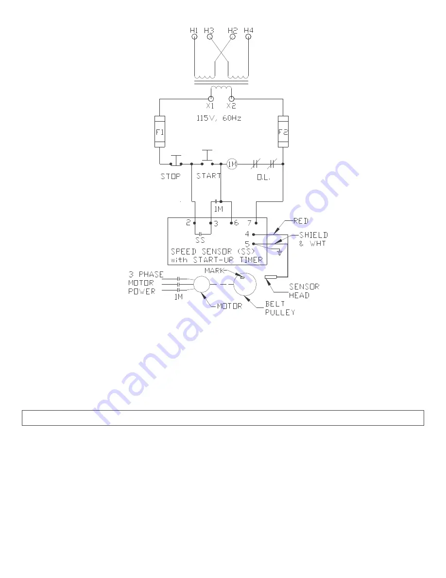
Figure 4 – Elementary Conveyor Control
Operating sequence:
1. Start button picks 1M coil and speed sensor.
2. 1M and SS contacts close to hold 1M and speed sensor.
3. Motor starts. If correct speed is reached before timeout, SS contacts remain closed ; otherwise SS opens, 1M drops, motor stops.
4. If speed sensor is set for underspeed detection and machine slows below setpoint, SS opens, 1M drops, and motor stops.
5. If speed sensor is set for overspeed detection and machine speed exceeds setpoint, SS opens, 1M drops, and motor stops.
6.0 OPERATION
6.1
Preliminary circuit tests.
If all connections are made as shown on the
connection diagram, above, the system should be
ready for power. To ensure proper wiring, perform a
visual inspection and ring-out before power is
applied for the first time.
6.2
Setup Procedure
If the speed sensor contacts are interlocking the
RUN circuit as shown in Figure 4, they should be
jumpered or bypassed until the sensor is set up.
Select the operating range by moving the J5 jumper
to the proper setting. Do not remove the J2 jumper
or move it from the “run” position as erratic
operation may occur.
6.2.1 Under Speed Detection
Move the J4 jumper to the lower (underspeed)
location. If startup delay is desired, rotate the
startup delay control to the desired time. Set the


