4
G
K
J
H
F
E
L
O
M
N
D
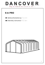
PERGOLA ANATOMY
CARE AND MAINTENANCE
142-13/16"
362,7 cm)
120"
304,8 cm)
109-3/4"
(278,8 cm)
132-1/16"
(335,4 cm)
INSIDE
POST
INSIDE
POST
OUTSIDE
POST
OUTSIDE
POST
❑
The wood in your pergola has been treated with a process called ProWood Micro for resistance to fungal decay and
insect infestation.
❑
The color of your pergola is from a process called MicroShade ™ and involves adding pigment into the wood as it is
pressure treated. This process results in colorant throughout the wood which helps minimize surface markings being
visible. The appearance of your pergola with MicroShade will last about two years with no stain application. Over time
the color of the pergola wood will slightly darken.
❑
If you want, you may apply a water repellent which will bene
fi
t the wood and help minimize splitting, checking and
surface cracking.
❑
Checking, splitting and surface cracking are characteristics of all wooden structures. This is caused by varying
seasonal temperatures and moisture conditions. To minimize this checking and/or cracking you may coat your pergola
with a water repellent.
❑
A wood stain may be applied to your pergola if you choose.
❑
For minor touch-up we have included sandpaper and some MicroShade concentrate. Refer to page 26 of this manual
for our suggested procedure for minor touch-up.
❑
We suggest you inspect all hardware and fasteners used to assemble your pergola for any deterioration or looseness.
Re-tighten hardware as required.
90-1/2"
229,9 cm)