background image

Ribcage Installation: Part 2 - Assembly 


www.back-bone.ca | [email protected] 

8         

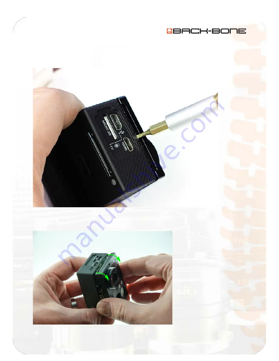
1-3 Remove Assembly From Housing 

Insert a small flat screw driver into the small slot located between the faceplate and the USB/HDMI 
ports. Use it to pop the edge of the housing up over the USB and HDMI ports. 


Gently wiggle the unit to work it out of the housing, taking care not to damage the tiny ribbon cable 
connecting the assembly to the housing. 


Summary of Contents for Ribcage v2.0

Page 1: ...Ribcage v2 0 Upgrade Kit Install Guide Back Bone V2 0 ...

Page 2: ...ve M12 Ring 13 1 7 Remove Image Sensor and Standoff 14 Section 2 Assembly 15 2 1 Insert O Ring 15 2 2 Attach CMOS Sensor to Cover Plate 16 2 3 Attach the Cover Plate to the PCB Plate 20 2 4 Connect flexible PCB jumper to PCB plate 21 2 5 Functionality Test 28 2 6 Put Ribcage Assembly Back Into Housing 29 2 7 Release Cover Plate Screws 30 2 8 Insert Original Corner Screws 31 2 9 Screw on Cover Plat...

Page 3: ...on 1 Before You Get Started Included With Your Kit ITEM DESCRIPTION QUANTITY 1 650nm IR cut filter 2 2 M12 ring 1 3 Plastic standoff 1 4 IR Cut Holder 2 5 Filter Stickers 4 6 L key 0 050 Hex 1 7 L key 0 035 Hex 1 8 0 80 x 1 4 Philips screw 4 9 Nylon tip set screw 1 10 Rubber O Ring 1 ...

Page 4: ...Ribcage Installation Part 2 Assembly www back bone ca support back bone ca 3 Figure A ...

Page 5: ...itional tightening is not required 8 By applying this or any modifications to your GoPro devices you will VOID any warranties 9 Back Bone takes no responsibility in your ability to use this modification 10 The Ribcage v2 Upgrade kit is provide as is and without warranty 11 Disclaimer Ribcage is a product of Back Bone Gear Inc and is not manufactured distributed or endorsed by Woodman Labs Inc the ...

Page 6: ... or the larger of the two L keys that came with your kit or camera to remove the screws holding on the tripod mount 0 050 Hex Remove the 5mm C Mount spacer ring Use your small L Key 0 035 Hex to loosen the set screw on the large CS Mount ring Unscrew the ring to loosen Turn the camera so that the front is facing the floor Continue to unscrew the ring until it comes free The IR cut filter should dr...

Page 7: ...he 4 screws holding on the Ribcage faceplate Lift the plate slightly and rotate about 10 degrees to reveal the four corner mounting screws Use your screwdriver to loosen and remove all four screws Make sure to keep them for later Remove the power button if it hasn t come out on its own Rotate the cover plate back into position ...

Page 8: ...Ribcage Installation Part 2 Assembly www back bone ca support back bone ca 7 Fasten the cover plate back down with one or two of the screws you removed ...

Page 9: ...nsert a small flat screw driver into the small slot located between the faceplate and the USB HDMI ports Use it to pop the edge of the housing up over the USB and HDMI ports Gently wiggle the unit to work it out of the housing taking care not to damage the tiny ribbon cable connecting the assembly to the housing ...

Page 10: ...Ribcage Installation Part 2 Assembly www back bone ca support back bone ca 9 To disconnect the ribbon flip up the black locking tab and slide the end of the ribbon out of the socket ...

Page 11: ...sor The tab connecting the image sensor ribbon to the main board is covered by a small piece of electrical tape Gently remove the tape Gently lift the lower right hand corner of the connector with your fingernail or a slim non metallic tool A small amount of upward pressure should pop the connector free ...

Page 12: ...t back bone ca 11 1 5 Remove Main Board Unlock the black locking tab holding in the LCD connector on the lower right Gently use your screw driver to pull the end of the connector from the socket Remove the small metallic screw holding the main board in position ...

Page 13: ...Ribcage Installation Part 2 Assembly www back bone ca support back bone ca 12 Next remove the main board by lifting it and moving it down and away from the CCD ribbon that was disconnected earlier ...

Page 14: ...the appearance but the following steps are the same for both Loosen each of the screws until the M12 ring comes free but do not remove the screws Depending on the version of the kit used you will need either a Philips 0 screw driver or the larger of your two L keys If the metal plate holding the image sensor has an open back take care not to dislodge the image sensor as it will become loose once t...

Page 15: ...ing the new ones provided in your upgrade kit At this point it s a great time to clean your CMOS sensor if any debris or smudges are visible NOTE At this point you may find it useful to view our v2 assembly video Some of the steps are not required but all of the steps outlined in the document going forward are pictured Links to relevant sections of this video are provided at the beginning of each ...

Page 16: ...Ring Video http youtu be I1kAaRuEa3o t 9m36s Take the supplied rubber O ring and cut it in half with a pair of scissors or a utility knife These will prevent the LED covers from being accidentally pushed back into the camera after re assembly Place each half of the O ring behind the LED covers in the faceplate ...

Page 17: ...tandoff over the image sensor If you look closely you will notice that one side of the plastic standoff is smoother than the other The smooth side should face forward when placed over the sensor If you find threading the screws difficult flip the plastic standoff over and try again You can also thread the screws through the standoff first and then remove them to make this step easier Take care not...

Page 18: ...k bone ca 17 Screw in four of the long silver screws provided through the holes in the back of the image sensor board and through the standoff Insert the image sensor with the plastic standoff back into the Ribcage cover plate so that the four holes line up correctly ...

Page 19: ... attaching the M12 ring Position the M12 ring with its set screw hole towards the top Screw the first socket screw into the M12 ring but do not tighten it It s important that the ring is flat against the plate as you engage the screws to ensure that no gap is present behind the ring when complete With the first screw loosely in position turn the M 12 ring to align the remaining three holes with th...

Page 20: ...ush with the cover plate and the 4 screws are snug ONLY i e tighten only to the point of contact Before continuing make sure there are no gaps behind the ring and it sits perfectly flat on the surface If you plan to use M12 lenses similar to the original GoPro lens insert the tiny set screw from your original M12 ring into the top of the new M12 ring using the small L key provided ...

Page 21: ...3m17s Attach the cover plate to the PCB plate Carefully thread the flexible connector through the opening in the PCB plate Once together connect them with one of the black screws provided Note when all the pieces are properly aligned the assembly fits together easily Never force any of the components instead check that they are seated properly and try again ...

Page 22: ...51s Optional If you wish you can choose to place a small piece of electrical tape on the back of the flexible 50 pin connector Next we ll connect the flexible jumper Be very careful to align the tiny 50 pin connectors together before exerting a small amount of pressure FORCING THE CONNECTORS TOGETHER WILL DAMAGE THEM ESPECIALLY IF THEY ARE NOT PROPERLY SEATED ...

Page 23: ...op the metal stiffener on the flexible PCB The tape will help isolate the metal stiffener from the bottom side of the PCB board that we will be attaching next Be sure to align the ribbon as closely as possible to the channel in the PCB plate The tape pictured is yellow but regular black electric tape is also a great choice ...

Page 24: ... bone ca support back bone ca 23 Bend the flexible PCB 90 degrees This will make attaching the PCB board in the next step easier Attach the small ribbon connector and flip down the black plastic locking mechanism to hold the LCD connector in place ...

Page 25: ... Assembly www back bone ca support back bone ca 24 Carefully move the flexible PCB jumper into the empty area where the wide angle lens assembly resided and match the through hole of the PCB board with the mount on the PCB plate ...

Page 26: ...ne ca 25 Attach the board with the small metallic 1 8 Philips screw provided Connect the flexible PCB jumper to the PCB board taking care to align the connectors prior to exerting any pressure to seat them together They should click together easily when properly aligned ...

Page 27: ...bone ca support back bone ca 26 Add a small piece of electrical tape to the upper side of the flexible PCB jumper to help isolate the jumper from the housing Note the tape shown here is yellow but standard black electrical tape is also recommended ...

Page 28: ...Ribcage Installation Part 2 Assembly www back bone ca support back bone ca 27 Part of the ribbon should remain tucked under the board slightly and bent over to form an S shape as pictured ...

Page 29: ...a quick test Take the GoPro battery and slide it onto the contacts located on the back of the camera Hold the battery in place and press the power button If the camera powers on and you are able to switch modes everything is good If the camera doesn t power on or you can t change modes ensure your battery is charged double check your connections and try again ...

Page 30: ...ousing If you have a Hero3 make sure you re attach the small ribbon connected to the housing Re insert the ribbon into the connection socket as pictured and click down the black locking mechanism to hold it in place This is not required for Hero3 Take the Ribcage assembly and angle it back into the housing ensuring the HDMI and USB ports properly mate with their openings and the assembly is fully ...

Page 31: ...upport back bone ca 30 2 7 Release Cover Plate Screws Video http youtu be I1kAaRuEa3o t 17m55s Release the screw holding on the new cover plate Separate the plate slightly and rotate it about ten degrees to reveal the four screw holes located in the corners ...

Page 32: ...allation Part 2 Assembly www back bone ca support back bone ca 31 2 8 Insert Original Corner Screws Video http youtu be I1kAaRuEa3o t 18m17s Insert the original four corner fastening screws Tighten them until snug ...

Page 33: ...port back bone ca 32 2 9 Screw on Cover Plate Video http youtu be I1kAaRuEa3o t 18m56s Next turn the unit over and place the power button in position within the cover plate Guide it in with your screw driver if necessary Click the cover plate back into place ...

Page 34: ...faceplate with four of the black screws provided Loosely fit all four screws before tightening all the way Do not over tighten A snug fit is all that s required Note In some cases debris may have worked its way into the threads Use your puffer to clear it out if threading the screw is difficult ...

Page 35: ...ne ca 34 2 10 Install the IR Cut Filter Video http youtu be I1kAaRuEa3o t 19m52s Now we ll prepare the IR cut filter You will need the filters filter holders and circular black stickers from your kit Cut the filter pack in half with a pair of scissors or a utility knife ...

Page 36: ...way the plastic film from one of the filters Pop in into the socket in one of the filter holders Note It s best to handle the filter by the edges to avoid adding smudges Set aside the backing paper for use in a moment Now take a utility knife and remove one of the stickers from the backing ...

Page 37: ...area you use hasn t been touched or you might transfer oil from your fingers to the filter Gently press down to fix the sticker in place Now is a good time to clean the filter if required Note Make sure the sticker is perfectly flat with no lifted edges and trim any excess that hangs over the side An incorrectly applied sticker may make inserting and removing the filter tray more difficult Spare s...

Page 38: ...sor cleaning tools to make sure it s crystal clear A magnifying glass is a handy tool to spot any tiny debris We recommend the Kinetronics SpeckGrabber Pro Cleaning Kit for cleaning the sensor when needed Next we ll add the IR cut filter We recommend that you position the IR cut cartridge with the square opening facing forward This will protect the filter and sensor in case you happen to screw in ...

Page 39: ...bly www back bone ca support back bone ca 38 Take one of the two filter cartridges provided and slide it into the slot at the base of the M12 ring Use your screw driver to move it into place so that it s centered over the image sensor ...

Page 40: ...g Tighten it until snug to keep the IR filter in place Note use the smallest L key provided If you ever want to remove the filter for night vision the best method is to loosen the set screw and push it out with the spare filter cartridge Note we don t recommend pushing it out with any tools as there is a chance they can make contact with the sensor ...

Page 41: ... support back bone ca 40 2 11 Attach the Mounting Rings Video http youtu be I1kAaRuEa3o t 22m18s Screw the CS Mount ring into place over the M12 ring Insert the remaining tiny set screw into the CS ring and tighten until snug using the provided Allen key ...

Page 42: ...lation Part 2 Assembly www back bone ca support back bone ca 41 In order to attach C Mount lenses attach the 5mm C Mount spacer ring that came with the original kit Use a puffer to remove any debris from the assembly ...

Page 43: ...Ribcage Installation Part 2 Assembly www back bone ca support back bone ca 42 It s recommended that you use the protective cap when no lens is attached ...

Page 44: ...Ribcage Installation Part 2 Assembly www back bone ca support back bone ca 43 2 14 Re attach Battery and Accessories Video http youtu be I1kAaRuEa3o t 23m19s Re attach the battery and accessories ...

Page 45: ...he tripod plate using the two original black screws If the screw requires any force to put in it is best to back it off and try again The screws will go in easily when properly aligned Loosely fit both screws before tightening all the way Do not over tighten If the screws feel tight back them off slightly and make sure the threads are properly aligned ...

Page 46: ...tion Part 2 Assembly www back bone ca support back bone ca 45 2 12 Done Video http youtu be I1kAaRuEa3o t 24m21s Now we re all done Go out and enjoy your upgraded camera and have fun experimenting with different lenses ...

Reviews: