Microprocessor Module Replacement Kit for the Remote Display
3015-5577 Rev 2
3
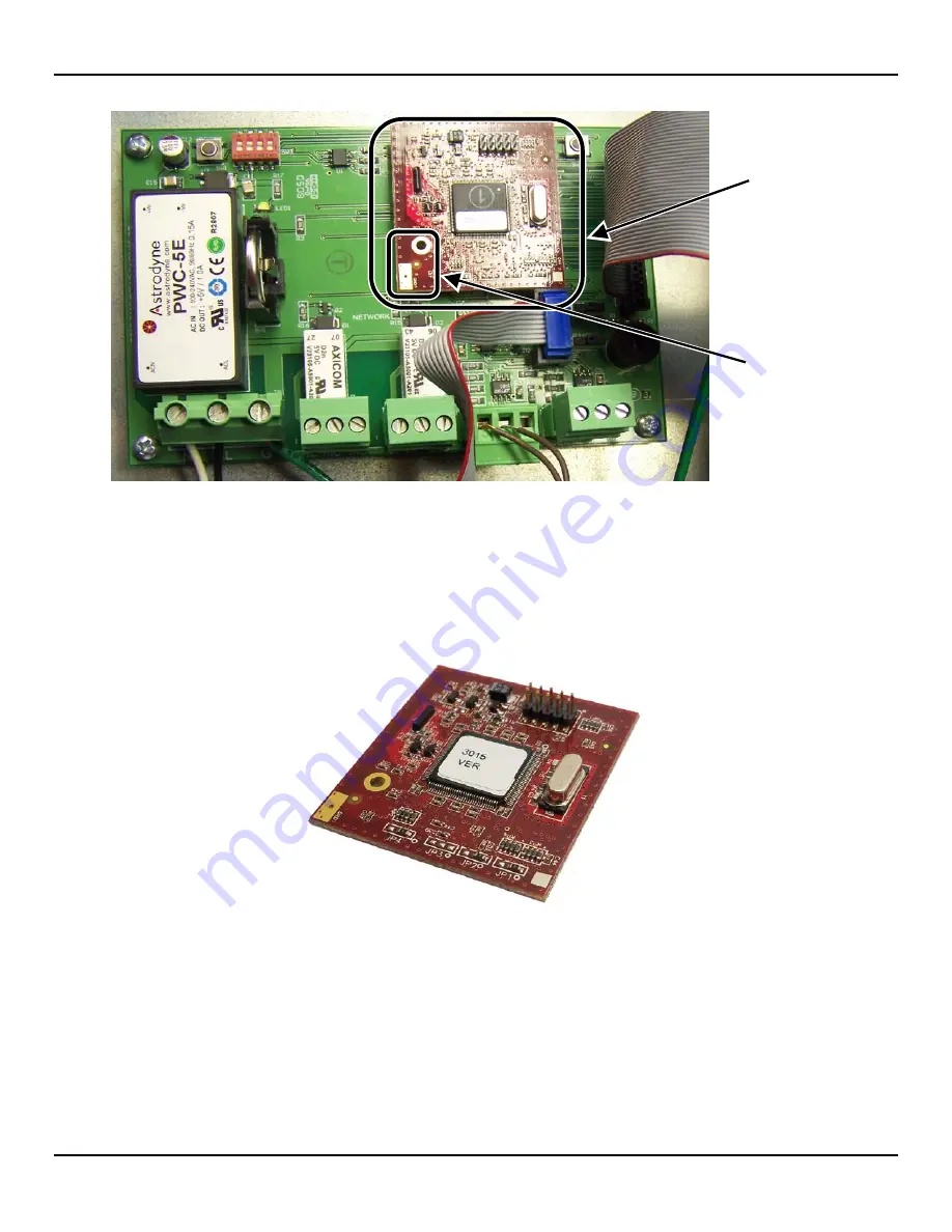
Figure 1. Location of Microprocessor Module Inside the PAGM Housing
5. Note the orientation of the module, specifically the gold tab and hole oriented on the bottom left of the board.
6. Grasp the left and right edges of the microprocessor module and gently pull straight out while rocking left to right,
until it comes free of the socket.
7. Dispose of the removed microprocessor module in accordance with local regulations for electronic equipment.
Figure 2. Microprocessor Module Removed from the RD’s Main Board
5. Installing the New Microprocessor Module
Install the new microprocessor module by following the steps below. Depending on your hardware and the replacement
kit that you receive, there are two different installation procedures. One method accommodates different hole sizes in the
microprocessor board and the mother board, and uses two screws (0001-1552) and a female-threaded spacer (0304-
8289). The other method accommodates the newer microprocessor board and mother board which have the same size
holes, and uses a snap-in spacer (0304-8459). Follow the installation option that corresponds to the hardware that is
supplied with your kit.
Microprocessor
Module
Note Position of
Gold Tab and
Hole (Bottom
Left)


