background image

DUO DMX


Gateway


Programming


DUO DMX


Gateway


b.a.b-technologie gmbh  21 


5.2.11


EXPORT AND IMPORT SCENES 

In addition, you can save individual scenes separately. This is useful if you need the same 
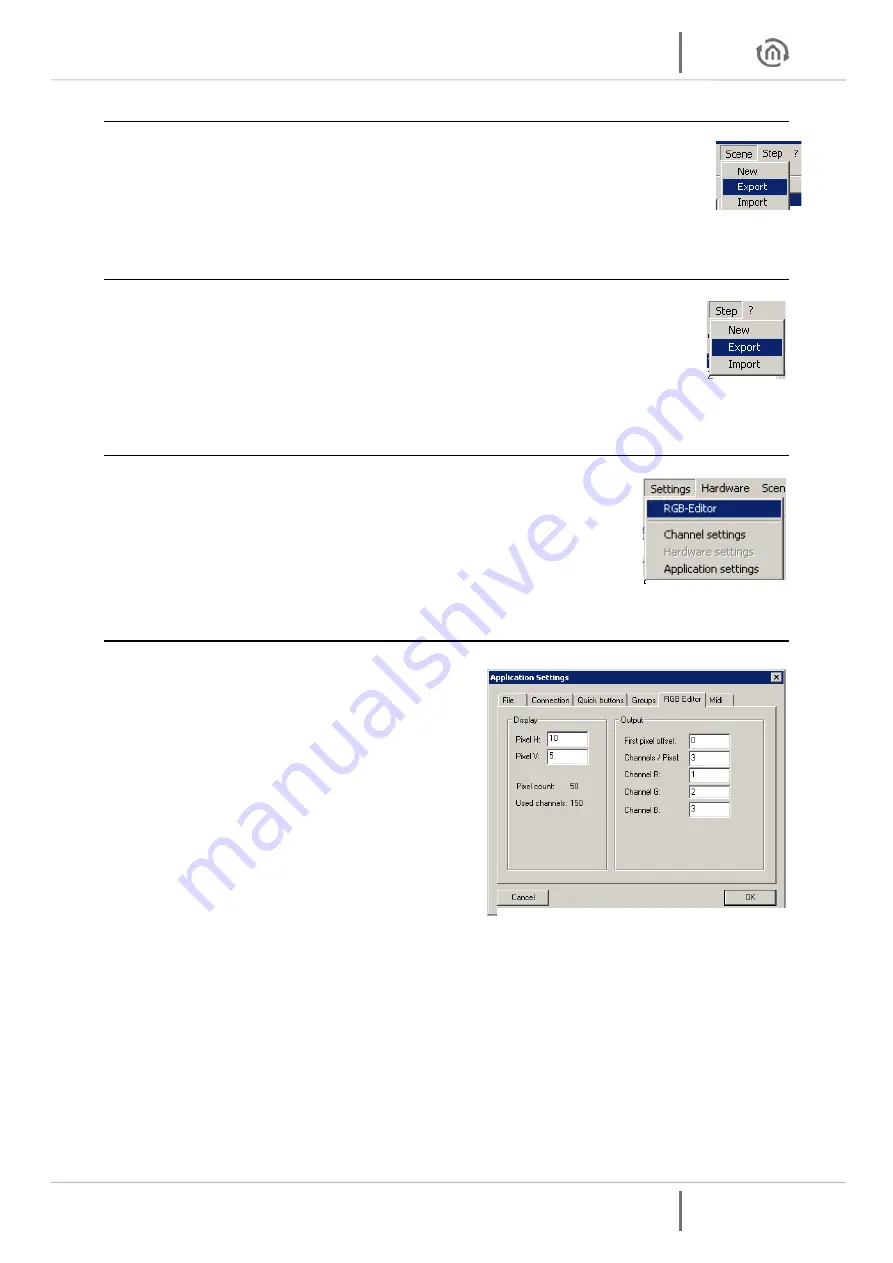
scene in another project. To save individual scenes using the menu Scene

 -> Export

. The 

saved file has the extension "* scn.".  With the menu 

Scene -> Import

 an exported scene in 

your project is added. 


5.2.12


EXPORT AND IMPORT OF STEPS 

The separate storage of Steps is analogous to these of the scenes. To save individual steps 
using the menu 

Step > Export

. The saved file has the extension "*. stp". The menu item 

Step> Import

 you can add a step to the end of the step list. 


5.2.13


RGB EDITOR 

The RGB Editor is specifically designed for the production of light images with 
LED stripes or LED panels. Enable the DMX-editor in the menu under 

Settings> 

RGB Editor

. The sliders are replaced by colored rectangles. These represent the 

individual RGB channels. 


5.2.13.1


CONFIGURE RGB EDITOR  

You can configure the display and the assignment of 
the RGB settings to the DMX channels. To do this, 
select the menu item 

Settings> Application settings


and then go to the Tab 

RGB


Editor

 
This opens a dialog where you will find the following 
settings: 


Pixel H:

 Indicates how many RGB fields should 

be arranged horizontally. 


Pixel V:

 Indicates how many RGB fields should 

be arranged vertically. 


First Pixel offset:

 Specifies how many DMX 

channels are before the first pixel 


Channels/Pixel:

 Specifies how many DMX 

channels can be assigned to a pixel. Follow all 
RGB channels directly on one another, is here to provide third More control channels or a 
channel W are used, must be stated here also that much more. 


Example:

 The DMX4all LED dimmer is indicated here since five channels for a total of 5 RGBW 

and STROBE are used. 


Channel R:

 Specifies which (first) channel is assigned to used RED 


Channel G:

 Indicates which channel is assigned to the used GREEN 


Channel B:

 Indicates which channels is assigned to used BLUE 


ATTENTION:  

RGB fields to a maximum of 512 channels can be predefined.


Figure 26: Export 

and Import of 

Steps 

Figure 27: start RGB 

Editor 

Figure 28: RGB Editor Configuration 

Figure 25: Scene 

Export and Import 

Summary of Contents for 12000

Page 1: ...b a b technologie gmbh DUO DMX Gateway documentation Artikel Nr 12000 12010 12020 12030 Documentation version IV Actual state 07 2012 Date 8 August 2013 EN...

Page 2: ...ent DUO DMX Gateway 2 b a b technologie gmbh DUO DMX Gateway b a b technologie gmbh im INHOUSE Dortmund Rosemeyerstr 14 44139 Dortmund info bab tec de Tel 49 0 231 476 425 30 Fax 49 0 231 476 425 59 w...

Page 3: ...ve and load projects 20 5 2 11 Export and Import scenes 21 5 2 12 Export and Import of Steps 21 5 2 13 RGB Editor 21 5 2 13 1 Configure RGB Editor 21 5 2 13 2 Use of RGB Editor 22 5 2 14 Channel SoftP...

Page 4: ...ure 19 Steps erstellen 17 Figure 20 Color Picker selection 18 Figure 21 Color Picker different views 18 Figure 22 define DMX groups 19 Figure 23 DMX Master Control 20 Figure 24 Load and save projects...

Page 5: ...ng installation Due to its compact measures it can be used for complicated mounting lays too The device provides 2 DMX output channels and so it is able to handle two different circuits at the same ti...

Page 6: ...Figure 1 DUO DMX Gateway with grounding clips DIN Rail Bar adapter The adapter is fixed on the chassis with 2 screws part of delivery Please note that the adapter only may be screwed in the two folde...

Page 7: ...Therefore the device must be connected to the network too Device model KNX TP As KNX Twisted Pair version the device is directly connected to the twisted pair wiring of the KNX bus For this purpose th...

Page 8: ...st install the software DMX Configurator The setup file for installing the software DMX Configurator can be found on the CD or can be downloaded at www bab tec de The Software is MS Windows based Inst...

Page 9: ...if the device is in operation Start the DMX Configurator and browse to the menu Extensions DUO DMX Gateway Figure 5 DMX Configurator extensions You will be asked to choose the device type you are usin...

Page 10: ...resp Lan EnOcean and change the IP address corresponding your desires Figure 8 DMX Configurator IP Adress Settings Allocate a device name Press the Search button and check the current settings of the...

Page 11: ...k settings of your PC and the DUO DMX Gateway once again Figure 11 DMX Configurator transfer configuration After that please leave the window KNX or EnOcean by clicking the OK button and save the curr...

Page 12: ...later If you have an older version of the DMX Configurator please download the actual one from our homepage Older project data Projects from older versions of DMX Configurator can be opened without pr...

Page 13: ...tor to be started The preview will be sent via Broadcast signals into the network 2 Unicast Preview Only a selected DUO DMX Gateway receives the preview signals It is important to note that the desire...

Page 14: ...nd the DUO DMX Gateway must reside in this case in the same area network subnet To set the DUO DMX gateway to the desired IP address range please have a look at the section Extensions Firewall setting...

Page 15: ...g s on the DMX controllers of the DMX Configurator directly on the DMX end devices The software is supplied with the CD and is suitable for all current Windows systems 5 2 1 USER INTERFACE The user in...

Page 16: ...e scene list This name can be edited freely The Button copies all selected scenes including all their steps deletes the selected scenes including all their steps The arrow box serves for displacing th...

Page 17: ...at once by pressing these buttons Per step different DMX values for each channel can be set By stringing together several steps with various DMX values a dynamic light image can be created The step l...

Page 18: ...button must be clicked The dialogue of the Color Picker is available in 2 different views Left the standard representation normal style and the on the right color distribution as color wheel round st...

Page 19: ...he DMX channels must be entered which form the group Here the separation of DMX channels is made with a semicolon One DMX channel can belong to different groups After you define the groups you will se...

Page 20: ...ion is executed after the last step in a scene is set by the selection box under the step list Repeat after last step The scene is running in an endless loop Stop after last step The scene will stop t...

Page 21: ...lay and the assignment of the RGB settings to the DMX channels To do this select the menu item Settings Application settings and then go to the Tab RGB Editor This opens a dialog where you will find t...

Page 22: ...ing the right mouse button on the RGB box It now opens a menu from which you select Color Picker This will open the Color Picker window as already known In order to copy colors from one field to anoth...

Page 23: ...ching of existing scenes to a other existing installation Thus the scenes remain unchanged and only the assignment of the individual channels must be new No double seizure In order to terminate the in...

Page 24: ...icture above for address 11 Standard color channel Furthermore an additional info for each channel can be deposit In standard this is an info over the color that is controlled by this DMX address For...

Page 25: ...t loaded Load specified file it will load the specified project With the project file is selected Load last opened file The last opened project is loaded 5 2 17 STORAGE LEVEL INDICATOR Since DMX Confi...

Page 26: ...X or an EnOcean model Overview of unit types technologies KNX BMX 12000 Extension for eibPort 12010 KNXnet IP 12020 KNX TP EnOcean 12030 EnOcean If the selection is made the configuration window for e...

Page 27: ...s is set Broadcast Preview In addition if a device in the list DMX Gateway is marked too the preview is only valid for this device Unicast Preview In this case the PC and the gateway have to be in the...

Page 28: ...on the middle group Figure 36 set group addresses 2 Deleting entries To delete an entry highlight it and press the Delete key on your keyboard USE ESF DATA To link the group addresses from a file cal...

Page 29: ...ft side is drawn to the corresponding scene on the right side Then the group address is shown below the scene Figure 38 linking group addresses to scenes Each scene can be launched from any number of...

Page 30: ...way EnOcean It lacks the configuration items for the KNX multicast address and for the KNX phys Address The explanation of the remaining menu items see the chapter Configuring KNX 5 3 3 1 LINKING OF E...

Page 31: ...can start and stop or pause two different scenes The behavior of the scenes in a stop message is in the tab Lan EnOcean can be determined Figure 41 EnOcean Linking of scenes More than one profile can...

Page 32: ...e amplifies the range of the signal There are two choices Figure 43 EnOcean Extension Repeater Functionality 1 Check boxes to activate the repeater EnOcean function EnOcean repeaters The unit will rep...

Page 33: ...ddition to storing as DMX project file each project can also be exported as a so called HEX file too This file format is required to transmit the configuration data to the DUO DMX gateway This configu...

Page 34: ...must be named dmxknx fir Unplug the DMX Duo Gateway from the power supply and insert the SD card into the SD card slot Press the button and hold it down while you connect the power supply again Wait...

Page 35: ...gether they must communicate over the same port number BMX Port Cause in the DUO DMX Gateway the port number cannot be changed it must be set correctly in the eibPort About the System Configuration Ad...

Page 36: ...ORT JOB LINKING FACILITIES If the messages should be transferred over the BMX protocol to the Duo DMX Gateway the linking facilities job is used This job is also described in the documentation of eibP...

Page 37: ...pled 1 1 to EIB Installation 2 6 6 All group addresses from main group 6 of EIB installation 1 will be coupled 1 1 with main group 6 of the EIB installation 2 7 17 All group addresses of main group 7...

Page 38: ...ols ESF Upload data maintenance Insert the wanted addresses in eibPort and export it as an ESF file ESF data from the ETS To generate the desired data with ETS you need the application of a device whi...

Page 39: ...th great care and in good faith However errors can not be excluded completely For this reason we have an incentive to point out that we do not guarantee or assume legal responsibility or liability for...

Reviews: