background image

19

HOW TO OPERATE

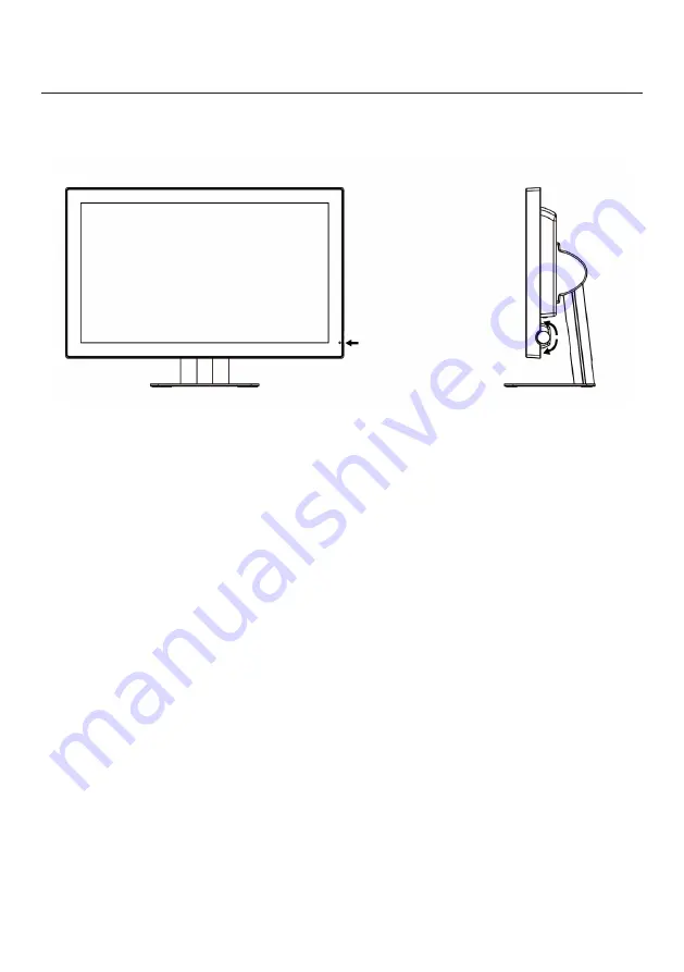
Control Dial

The Control Dial is a multi-functional device located behind the LED Indicator on the 

right side of the front bezel. It has three movements-rotate upward, rotate down-

ward and press inward as a button.

1. Power On/Off

Press the Control Dial to power the unit on from the off stage (the LED is off). To turn the 
poweroff, press the Control Dial and hold for at least 1 second until the LED turns off.

2. OSD Control

While the monitor is on (green LED and image on the screen), pressing on the Con-

trol Dial activates the OSD. While the OSD menu is active, use the three way move

-

ments of the Control Dial to adjust the monitor.
Rotate Downward: Move Up/Right, Increase, Larger, More

Rotate Upward: Move Down/Left, Decrease, Smaller, Less
Button Press: Execute, Do, Save

LED Indicator

This LED indicator turns green when the power is switched ON and the power cord is pro-

perly attached. It turns amber when the monitor goes into a power saving mode (Active 
Off). Please refer to the Power Management section of manual for more information.

LED Indicator

Control 

Dial

Names and Functions of Each Part

Summary of Contents for e-medic 2011945e

Page 1: ...1 Displays e medic AM AM Touch Handbuch Manual...

Page 2: ...Photographs and schematic diagrams used in this document are for illustration purposes only The actual product may vary This document contains proprietary information protected by copyright No part of...

Page 3: ...rective 93 42 EEC concerning Medical Device Use this product after carefully reading this Manual and understan ding the contents Store this manual with care as close as possible so that you can read w...

Page 4: ...lose to you as possible and in safe custody If you have lost the manual contact your dealer We will reissue a manual The names of companies and products are registered brand names or brand names Revis...

Page 5: ...bols 9 Cleaning instructions 11 Disposal of the unit 11 Auxiliaries 12 Application and function description 13 Features 14 Connection method 15 How to operate 19 Charts of OSD adjustment functions 20...

Page 6: ...ment not complying with UL EN IEC 60601 1 shall be kept outside the patient environment as defined on the systems standard III Intended Use This device displays video images from medical equipment It...

Page 7: ...more of the following measures Reorient or relocate the receiving antenna Increase the separation between the equipment and receiver Connect the equipment into an outlet on a circuit different from th...

Page 8: ...r LCD monitor uses an AC DC Adapter Only use the Adapter which accompanied with this device Use of another AC DC Adapter may cause a malfunction or danger If your LCD monitor does not operate normally...

Page 9: ...cy interference regulations Fragile Handle with care Indicates front Keep dry Protect from rain ON Power connection to the mains Recycled materials or may be recycled Stacking limit by number Standby...

Page 10: ...zed representative of the manufacturer for informati on concerning the decommissioning of your equipment ATTENTION Consult accompanying documents DANGER Shock Hazard Dangerous voltage To reduce the ri...

Page 11: ...the LCD panel are isopropyl alcohol without abrasive non ammonic glass cleaner and watered down neutral cleaning solution Do not use organic solvent such as acetone and toluene When the screen has du...

Page 12: ...ake sure that all items listed below are present in your package e medicTM Display AM The LCD monitor User s manual AC Power cord VGA Cable DP Cable DVI Cable Optional Items These are optional items a...

Page 13: ...er for wall or swivel arm mounting Function Description The medical flat screen displays are built into a slim and ergonomic housing The e medic models are optional equipped with a protection glass or...

Page 14: ...n corresponding to the resolution from VGA 640x480 to FHD 1920x1080 This is also compliant with VESA standard display mode Power management This unit has loaded the power management system The power m...

Page 15: ...ed by contacting dealer directly VGA connector The VGA cable is transmitting the image data to your flat screen The cable has two 15pin D Sub VGA connectors to connect to your graphic adapter Connect...

Page 16: ...Monitor If you intend to mount the monitor on the wall arm we strongly recommend that you use only UL approved wall arm mount kits with attached M4 10mm screws and can load more than monitor weight th...

Page 17: ...e it has been securely and safely installed Caution When mounting the monitor take care to tighten the retention screws or bolts until fully secure but do not over tighten Over tightening the retentio...

Page 18: ...them Step 6 Insert the four monitor mounting screws provided in the wall mounting kit into the four screw holes on the rear panel of the LCD Monitor and tighten until the screw shank is secured again...

Page 19: ...itor is on green LED and image on the screen pressing on the Con trol Dial activates the OSD While the OSD menu is active use the three way move ments of the Control Dial to adjust the monitor Rotate...

Page 20: ...ial inward to select that control or to activate that function Depending on the control you selected a submenu of the control with a status bar will appear The status bar indicates in which direction...

Page 21: ...Close OSD window No Return to Phase Menu Change manually Brightness Selecting this control allows you to make adjustments to the brightness level of the display screen in the scale of 0 to 100 Contra...

Page 22: ...e the display moves to the right and vice versa For the digital input DVI or Display Port this function is not available V Position Adjust the vertical position of the display When rotating control di...

Page 23: ...hite for general use and CAD CAM 9300K is a fixed value by the manufacturer User cannot change the setting value Neutral White close to natural light used for publishing trade 6500K is a fixed value b...

Page 24: ...is and vice versa Blue Adjust blue and equivalent colors at the range from 0 to 100 The greater the value is the deeper the color is and vice versa Gamma 1 8 Gamma 1 8 mode of brightness and gamma pr...

Page 25: ...otating the control knob As the value gets larger the screen moves to the right and vice versa The adjustable range is from 0 to 100 For the digital input DVI or Display Port this function is not avai...

Page 26: ...26 Management Scaling...

Page 27: ...D H Position Adjust the horizontal position of OSD When rotating control dial clockwise OSD moves to the right and vice versa OSD V Position Adjust the vertical position of OSD When rotating control d...

Page 28: ...s control to select the language you want English Display OSD in English Francais Display OSD in Francais Deutsch Display OSD in Deutsch Italiano Display OSD in Italiano Espanol Display OSD in Espanol...

Page 29: ...In VGA input it supports Sync on green and the interlace timing can be displayed DVI Display signal from DVI connector 24 pin DVI Displayport Display signal from Displayport connector Recall Initiali...

Page 30: ...30 Mute To control the audio sound of monitor On mute Off no mute Volume Adjust the volume of the audio sound Selecting this control to volume a scaling At the range from 0 to 100...

Page 31: ...eve Plug Play Data reading from the color LCD display is done through a video signal cable which needs to be connected when Windows 95 98 Me 2000 or Windows XP is on NOTE 1 DDC Display Data channel an...

Page 32: ...32 Baaske Medical GmbH Co KG 32312 L bbecke www e medic com e medic Die Marke der Baaske Medical GmbH Co KG Rev 1 1 08 2020 Technical changes and errors expected...

Reviews: