background image


8

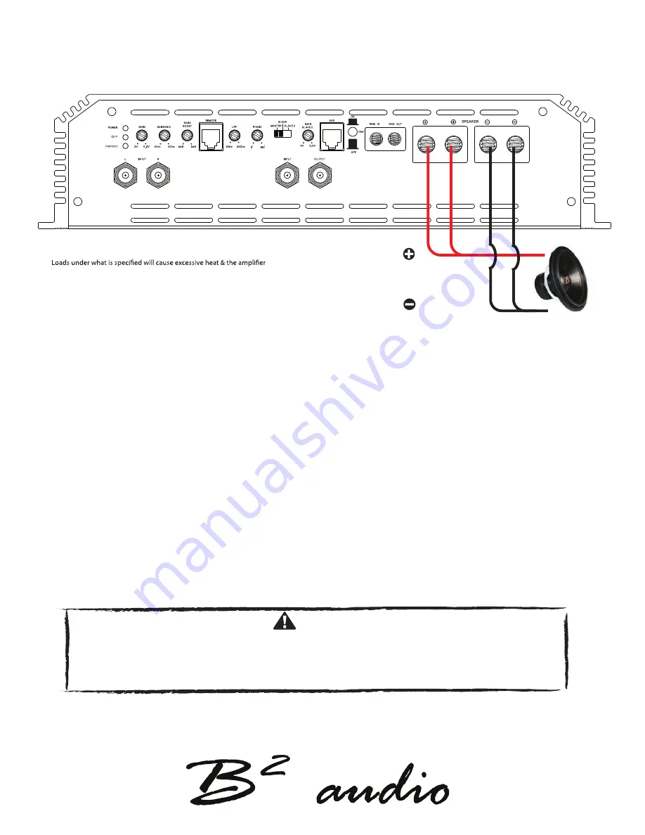
speaker connection

The Falcon / The Osprey


CAUTION


Installation of the amplifier shall be done in the following steps:

1. Connect the +12V wire, keep in mind this wire has to be fused at the battery as well. 2. Ensure the ground is 

appropriate, then connect it to the amplifier. 3. Connect the switched remote. 4. Reattach negative wire (ground) 

to the battery. 5. Operation over 16V  will cause the amplifier to go into protect & can void the warranty! 

We recommend using  minumum10 Ga speaker cables to acquire the intended performance & efficiency.

Run the speaker cables from your speakers to the amplifier’s mounting location. 

Ensure these are ran separately and away from high current cables and if possible the RCA cables as well. 

In all cases where cables are penetrating the vechile’s chassis use grommets to protect the cable. 

Connect the speaker wires according to the terminals on the speaker(s). Strip 3/8’’ / 1 cm of insulation of the end of 

each cable and twist the cable strands together tightly. Make sure there are no stray strands that could touch other 

cables or terminals as it can cause a short circut. 

Crimp spade plugs over the end of the cable or tin the ends with solder to provide a solid terminal.

Connect the cable ends to the amplifier as shown in the diagram. Note, the amplifier’s speaker terminals are 

internally bridged.

Speaker impedance 1 Ohm ~ 8 Ohm

will reach thermal at a faster rate & will eventually go into protect. 

Impedance load under 1 ohm is not warranted!

Summary of Contents for Zero Five The Falcon

Page 1: ...Zero Five The Falcon Zero8 The Osprey USER MANUAL PRODUCT ID Z5FALCOND19 Z8OSPREYD19...

Page 2: ...fering an advantage which will show the true value of the product To obtain the full potential of any amplifier to minimize failure it is advised to upgrade your stock electrical system Don t take any...

Page 3: ...62 x 12 4 x 2 95 Dimensions 500 x 315 x 75 mm 600 x 315 x 75 mm Continious output power RMS The Falcon 12 v 1 tHD 13 8 v 1 THD 14 4 v 1 THD 16 v 1 THD OUTPUT POWER 4 1500 W 2000 W 2300 W 2500 W OUTPUT...

Page 4: ...0 2v Master slave settings enables strapping of the amplifier Adjusts signal input voltage from the input source with another identical amplifier to achieve twice the power to match the amplifiers inp...

Page 5: ...n Connects to the vehicle s chassis Keep as short as Connects to the positivie terminal of the battery possible 20 50 cm Use minimum 0AWG cable For specified performance 0AWG cable is required for opt...

Page 6: ...n Connects to the vehicle s chassis Keep as short as Connects to the positivie terminal of the battery possible 20 50 cm Use minimum 0AWG cable For specified performance 0AWG cable is required for opt...

Page 7: ...ble to ensure correct operation Connect the power cables to the power terminal labeled as 12V The amplifier is not equipped with fuses so external fuses are required at both the battery and the amplif...

Page 8: ...separately and away from high current cables and if possible the RCA cables as well In all cases where cables are penetrating the vechile s chassis use grommets to protect the cable Connect the speake...

Page 9: ...egative speaker output on master to negative speaker output on slave Step 1 Connect RCA from Head Unit output source into master If only one output is available then use a Y split to connect both L R...

Page 10: ...10 The Falcon The Osprey Slave 2 control panel setting speaker wiring slave 2 slave 3...

Page 11: ...dB 2 34 Hz 0 30 dB 16 68 Hz 8 60 dB 30 170 Hz 8 90 dB 3 34 Hz 0 40 dB 17 76 Hz 8 70 dB 31 181 Hz 8 90 dB 4 35 Hz 0 50 dB 18 86 Hz 8 70 dB 32 185 Hz 8 90 dB 5 35 Hz 0 75 dB 19 100 Hz 8 80 dB 33 190 Hz...

Page 12: ...9 12...

Page 13: ...0 0 5 0 0 0 1 0 0 2 0 0 5 0 0 1 0 2 0 5 0 1 2 5 1 17944 0 15858 1 k 0 1 2 5 0 1 0 2 0 5 0 0 1 0 0 2 0 0 5 k 1 k 2 k 56 164k W dx 6 163 kW dy 1 02086 Color Sweep Trace Line Style Thick Data Axis Commen...

Page 14: ......

Reviews: