background image


4

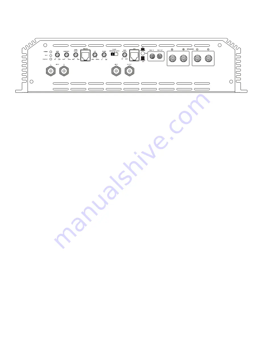
Panel layout

The Falcon / The Osprey

INPUT 


bass boost

RCA signal input for left & right channel. 


Level control of 0~9 dB @ 45 Hz. 

A minimum of 0.2V input signal is required for correct   


operation. Using only 1 input will minimize input signal


Remote level control port

and amplifier will need to be gained as such.


Connection of external signal level control with clip


indicator. Caution, it is not a volume knob and shall be

POWER  & PROTECTION INDICATOR  


adjusted in accordance with the amplifiers gain.

Power LED, blue light shows correct operation, 


Protect LED, red light shows general malfunction, faulty


LPF (LOW PASS FILTER 20 Hz ~200 Hz, 24 dB/oct) 

connection or thermal protection.   


Adjusts the cut off point for the low pass crossover


at the frequency chosen. 

clip INDICATOR

The LED will light up if signal is clipped. An occastional   

Phase 

flashing light is acceptable, a constant lit diode is not.   

Variable phase adjustment from 0 ~ 180


master / slave / slave 2 

GAIN (5V~0.2v) 


Master & slave settings enables strapping of the amplifier

Adjusts signal input voltage from the input source 


with another identical amplifier to achieve twice the power.

to match the amplifiers input stage. 


When set in master, this unit will be sending the


0.2 V ~ 5 V is the operational voltage.   


signal to the slave unit, that will have the switch set to

Voltages beyond may cause errors or damage to the    

input slave with the rca connected to the input.

input section.   


                Slave 2 setting will work as a daisy chain of subsequent 

        amplifiers. 

Here 

each 

amplifier 

will 

work 

independently, 

SUBSONIC         


but the signal input will be taken from the master amplifier’s

Variable subsonic setting from 10 Hz to 50 Hz.   


 output making gain matching easier. 

It is highly recommended to set it according to the tuning 

of your subwoofer enclosure to avoid unnecessary strain to 

Gain slave 2

your sound system.  


In daisy chain mode or by gain matching, voltage could 


eventually differ a few tenths. The slave 2 gain provides


fine tuning of the gain signal from the master amp’s output.

        avd

        Connection 

for 

external 

voltage 

display 

showing 

the 

true 

        input 

voltage 

for 

the 

amplifier. 


o

Summary of Contents for Zero Five The Falcon

Page 1: ...Zero Five The Falcon Zero8 The Osprey USER MANUAL PRODUCT ID Z5FALCOND19 Z8OSPREYD19...

Page 2: ...fering an advantage which will show the true value of the product To obtain the full potential of any amplifier to minimize failure it is advised to upgrade your stock electrical system Don t take any...

Page 3: ...62 x 12 4 x 2 95 Dimensions 500 x 315 x 75 mm 600 x 315 x 75 mm Continious output power RMS The Falcon 12 v 1 tHD 13 8 v 1 THD 14 4 v 1 THD 16 v 1 THD OUTPUT POWER 4 1500 W 2000 W 2300 W 2500 W OUTPUT...

Page 4: ...0 2v Master slave settings enables strapping of the amplifier Adjusts signal input voltage from the input source with another identical amplifier to achieve twice the power to match the amplifiers inp...

Page 5: ...n Connects to the vehicle s chassis Keep as short as Connects to the positivie terminal of the battery possible 20 50 cm Use minimum 0AWG cable For specified performance 0AWG cable is required for opt...

Page 6: ...n Connects to the vehicle s chassis Keep as short as Connects to the positivie terminal of the battery possible 20 50 cm Use minimum 0AWG cable For specified performance 0AWG cable is required for opt...

Page 7: ...ble to ensure correct operation Connect the power cables to the power terminal labeled as 12V The amplifier is not equipped with fuses so external fuses are required at both the battery and the amplif...

Page 8: ...separately and away from high current cables and if possible the RCA cables as well In all cases where cables are penetrating the vechile s chassis use grommets to protect the cable Connect the speake...

Page 9: ...egative speaker output on master to negative speaker output on slave Step 1 Connect RCA from Head Unit output source into master If only one output is available then use a Y split to connect both L R...

Page 10: ...10 The Falcon The Osprey Slave 2 control panel setting speaker wiring slave 2 slave 3...

Page 11: ...dB 2 34 Hz 0 30 dB 16 68 Hz 8 60 dB 30 170 Hz 8 90 dB 3 34 Hz 0 40 dB 17 76 Hz 8 70 dB 31 181 Hz 8 90 dB 4 35 Hz 0 50 dB 18 86 Hz 8 70 dB 32 185 Hz 8 90 dB 5 35 Hz 0 75 dB 19 100 Hz 8 80 dB 33 190 Hz...

Page 12: ...9 12...

Page 13: ...0 0 5 0 0 0 1 0 0 2 0 0 5 0 0 1 0 2 0 5 0 1 2 5 1 17944 0 15858 1 k 0 1 2 5 0 1 0 2 0 5 0 0 1 0 0 2 0 0 5 k 1 k 2 k 56 164k W dx 6 163 kW dy 1 02086 Color Sweep Trace Line Style Thick Data Axis Commen...

Page 14: ......

Reviews: