Installation
WIRING DIAGRAM FOR USE WITH:
- MR16
- PAR36/AR111
HOT
12V
12V
Fixture
NEUTRAL
Remote
Transformer
1. Remove temporary cover.
2. Make connections using silicone filled wire nuts
(provided) from OptiLock to secondary wiring.
See wiring diagram.
FOR USE WITH MR16
6a.
For Optional Accessory Holder:
Insert accessory
holder tabs into slots on OptiLock.
HP2
Shallow Housing - Standard MR16 & PAR36/AR111
Remote Transformer Installation
RELEASE DATE
10/13/2021
REFERENCE NUMBER
INS-2856-00
40429 Brickyard Drive • Madera, CA 93636 • USA
559.438.5800 • FAX 559.438.5900
www.bklighting.com • [email protected]
B-K LIGHTING
IMPORTANT SAFETY INFORMATION LISTED ON REVERSE
READ, FOLLOW, AND SAVE ALL SAFETY AND INSTALLATION INSTRUCTIONS
FOR USE WITH PAR36/AR111
5b. Turn accessory holder upside down and
remove retainer clip. Insert up to two (2)
accessories.
Insert the retainer clip back on.
Insert any accessory lens with the smooth
side towards the lamp. If using a honeycomb
baffle, position it farthest from the lamp.
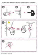
FOR USE WITH MR16
4a. Aim vertically by turning the thumbscrew on
OptiLock assembly.
FOR USE WITH PAR36/AR111
4b. Aim vertically by turning the #10 Phillips head
screw on OptiLock assembly with Phillips
screwdriver.
FOR USE WITH MR16
5a. Turn accessory holder upside down and remove
retainer clip. Insert up to two (2) accessories.
Insert the retainer clip back on.
Insert any accessory lens with the smooth side
towards the lamp. If using a honeycomb baffle,
position it farthest from the lamp.
3. Place OptiLock in HP2 housing and align keyhole
notch under one of three (3) #8 screw heads.
Rotate horizontally to desired aiming position,
then tighten two (2) #8 Phillips screws using
Phillips screwdriver. Install proper MR16 halogen
or PAR36/AR111 lamp according to instructions
on Lamp Installation Or Re-Lamping page.
OptiLock vary by product.