


40429 Brickyard Drive • Madera, CA 93636 • USA
559.438.5800 • FAX 559.438.5900
www.bklighting.com • [email protected]
B-K LIGHTING
IMPORTANT SAFETY INFORMATION LISTED ON REVERSE
READ, FOLLOW, AND SAVE ALL SAFETY AND INSTALLATION INSTRUCTIONS
RELEASED
10-30-18
REFERENCE
NUMBER
INS-2783-00
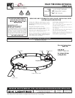
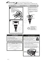
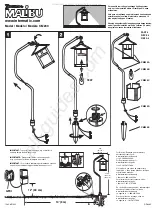
1. Mount knuckle onto suitable enclosure
according to designed lighting plan.
Fixture must be mounted to UL Listed
Junction Box or Enclosure.
2. Secure ½” NPS stem to mounting option. Secure
with provided locknut if applicable.
3. Pull branch circuit wiring. Make watertight
connections from branch circuit wiring to fixture
leads using waterproof wire connectors (By
Others) in splice location as per NEC. UL Listed
splice location required. Connect incoming
green ground wire to ground wire from fixture.
See wiring diagram.
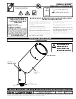
Fixture Installation
WIRING DIAGRAM
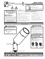
DENALI SERIES™
Integral Driver - Solid State LED
Standard Installation
All line voltage connections must be made in
compliance with the National Electrical Code.
Failure to do so will void warranty.
LINE
FIXTURE
COM
GROUND
LINE
COM
GROUND
7. Use 3/16” Allen wrench to loosen (1) 1/4”-28 x
1-1/4” stainless steel black oxide socket head cap
screw at the knuckle for vertical aiming purpose.
Tighten (1) 1/4”-28 x 1-1/4” stainless steel black
oxide socket head cap screw to 24” minimum to
48” maximum pounds to secure vertical aiming
position .
5. Rotate fixture at base and aim fixture to desired
horizontal location.
6. Tighten (1) 3/8”-16 x 3/8” stainless steel black
oxide set screw on the stem to secure horizontal
aiming position.
4. Use 3/16” Allen wrench to slightly loosen
(1) 3/8”-16 x 3/8” stainless steel black oxide set
screw on the stem for 360° aiming purpose.
Warning: Do not over tighten set screw.
Doing so will compromise O-ring seal and will
void warranty.
Knuckle Adjustment