background image

2

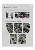
. Motherboard Installation :

)

2

(

)

1

(

Turn the screws counterclockwise

to remove the glass.

Put the motherboard in from behind.

(3)

Screw the motherboard onto the tray through the chassis.

Summary of Contents for CSAZ-807

Page 1: ...OVERDRIVE...

Page 2: ...lean on usually Available Fan Ports Water Cooling Isolated Chamber Easy Installation Cooler A pre cut hole for easy installation of CPU Cooler eliminating the need to remove the motherboard Accessorie...

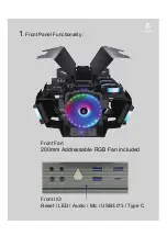
Page 3: ...1 Front Panel Functionality Front I O Reset LED Audio Mic USB3 0 3 Type C 200mm Addressable RGB Fan included Front Fan...

Page 4: ...2 Motherboard Installation 2 1 Turn the screws counterclockwise to remove the glass Put the motherboard in from behind 3 Screw the motherboard onto the tray through the chassis...

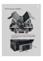
Page 5: ...3 Power Supply Installation Loosen the hand screws to remove the power supply bracket Attach the power supply to the bracket before placing it back in...

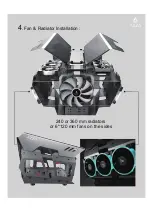
Page 6: ...4 Fan Radiator Installation 240 or 360 mm radiators or 6 120 mm fans on the sides...

Page 7: ...installation When installing a radiator Use long screws to affix the fan and radiator onto the chassis as shown When installing fans only Use nuts on the rear of the screw to affix the fan onto the ch...

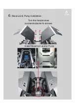
Page 8: ...Install Reservoir and or Pump Turn the handscrews counterclockwise to remove 6 Reservoir Pump Installation...

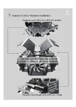
Page 9: ...Supports up to 280 mm or 360 mm radiator 7 Graphics Card or Radiator Installation Graphics Card length up to 400 mm 3 slots You can choose either side to install Graphics Cards or additional radiators...

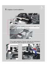
Page 10: ...hics Card Installation Attach the EVA foam supplied in the parts kit to support the graphics card PCI e cable installation Plug the cable onto the motherboard by passing the cable through the hole as...

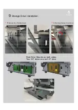
Page 11: ...Disk Drive Mounts on both sides 9 Storage Drive Installation 1 Remove the 2 handscrews 2 Lift and pull away to remove Disk Drive Mounts on both sides Two 2 5 drives or one 3 5 drive...

Page 12: ...Slide into cut out 10 Rear Cover Installation Screw to secure...

Page 13: ...ector to MB 6 1x4pin PWM fan connector to MB Functions 1 Total of 17 lighting modes 2 Lighting modes can be controlled by Reset or LED switch or can be controlled by MB A Magnet on the back of the hub...

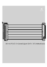
Page 14: ...C4 C1 C3 C2 J1 300 mm PCI E 3 0 Cable Support EATX ATX Motherboard...

Page 15: ......

Reviews: