The 845D-AV MAINBOARD
Ver 3.x
Page 17
Hardware Installation
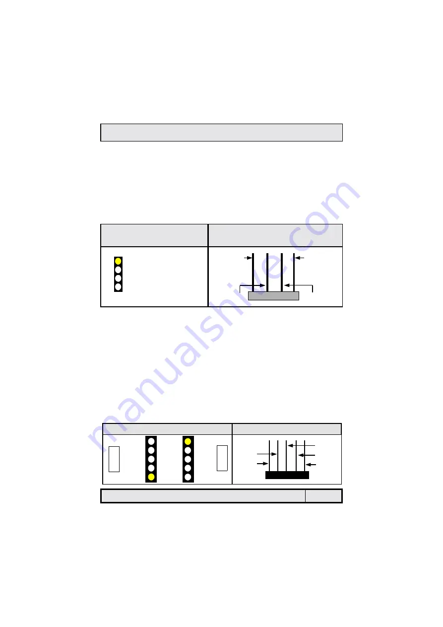
2.5.6. CD-IN/VIDEO-IN/AUX-IN Connector
Connector: CN 21 (CD-IN)/ CN 44 (VIDEO-IN) / CN 45 (AUX-IN)
Type: 4 pin un-housed
This 845D-AV mainboard has one CD-IN connector, AUX-IN connector and
VIDEO-IN connector. The CD-IN connector is used to connect the CD ROM au-
dio out and allows the system to receive audio input from the CD ROM. The
AUX-IN connector allows the system to receive signals from other audio de-
vices like a radio or tape. The VIDEO-IN connector allows the system to re-
ceive signals from devices like TV tuners, Video machines and Video cameras.
1 Left Channel CD/ AUX/ VIDEO-IN
2 Ground
3 Ground
4 Right Channel CD/ AUX/ VIDEO-IN
Top View of a CD/AUX/
VIDEO-IN Connector
Front View of a CD/AUX/VIDEO-IN
Connector
Right Channel
CD-IN/
AUX-IN/
VIDEO-IN
Left Channel
CD-IN/
AUX-IN/
VIDEO-IN
Ground
Ground
2.5.7. USB 3 and USB 4
Connector: CN 30 (USB 3)/CN 31 (USB 4)
Type: 5 pin
You already have two USB ports available, USB 1 and 2 (see external connec-
tors). The internal USB connectors allow you to add on an optional kit to ex-
pand the total number of USB ports available. The 845D-AV has two internal
USB connectors (CN30 and CN31). This enables you to use an extra two USB
devices. Cable for these additional connectors needs to be purchased sepa-
rately.
Note: These are not the standard USB connectors you find on the ATX PC99
connector. To connect USB devices you need to use an expansion cable
(purchased separately) that ends in a standard USB connector. Ask your re-
tailer for more details.
1 5V DC
2 Data-
3 Data+
4 Ground
5 Ground
Top View of a USB Port
Front View of a USB Port
5V DC
Ground
Ground
Data -
Data +
5V DC 1
Data– 2
Data+ 3
Ground 4
Ground 5
USB 3
USB 4


