


IQ Switch
®
ProxSense
®
Series
Copyright © Azoteq (Pty) Ltd 2022
IQS227-228BEV02 Evaluation Kit User Guide
Page
5
of
10
All Rights Reserved
Revision 1.0
November 2022
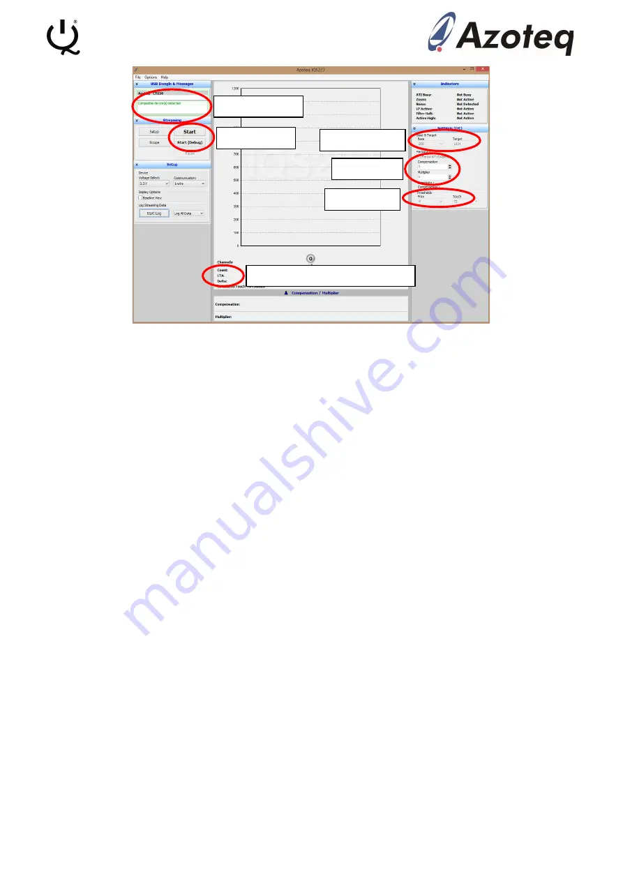
Figure 4.2 IQS227 GUI Start-up Screen
In the Message box, “Compatible device(s) detected” should be displayed. If the message “No
compatible device(s) connecte
d!” is displayed, there is a connection problem between the
computer and the CT210A. Make sure the CT210A is plugged in, the USB cable is a data cable
and not only for power delivery or try a different USB port.
Before the device can start streaming data, make sure the base board is setup correctly.
•
Move the ON/OFF slide switch to the OFF position
•
Move the 2-wire/1-wire slide switch to the 2-wire position
•
Make sure the ribbon cable is properly connected, the message “Device did not enter
debug mode” will be displayed in the Message box if there is a problem with the ribbon
cable connection
Click the
Start (Debug)
button to stream data. All the module boards included are default in
standalone mode. The boards can be programmed to Enable Streaming (use the Start button), but
then cannot be changed back to Standalone mode. If you click the Start button, you will receive a
“Timeout during operation” error in the Message box.
When everything is setup correctly and working in the data streaming mode, the GUI should look
similar to Figure 4.3
. The Message box now displays “Device streaming started”. The LED’s on the
module board will also turn on, this is not an error. In standalone mode the POUT and TOUT pins
of the IC are connec
ted to the 2 LED’s. In streaming mode the POUT and TOUT pins are used for
the I
2
C
communications and thus the 2 LED’s appear to be constantly on. There will also appear 2
grey bars in the GUI. The left one represents the Counts value (an inverse representation of the
measured capacitance) and the right one the LTA value.
Under the Settings (I
2
C) menu is some settings that can be changed. For the Green and Blue
module boards “Partial ATI Enabled” will be ticked and for the Black board it will not be ticked as
default. During ATI, the internal circuitry will try to get the Count value as close as possible to the
Target value by adjusting the Compensation and Multiplier fields. The Multiplier field acts as a
course adjustment to the Count value and the Compensation field acts as a fine adjustment.
Message box
Start button
Counts, LTA and Delta values
Base, Target
Partial ATI
Thresholds


