


IQ Switch
®
ProxSense
®
Series
Copyright © Azoteq (Pty) Ltd 2022
IQS227-228BEV02 Evaluation Kit User Guide
Page
4
of
10
All Rights Reserved
Revision 1.0
November 2022
4 Data Streaming Operation
The device can also be connected to a computer via the Azoteq CT210A and the data streamed.
The difference between the module boards will become clear when visualised on a computer.
4.1 Setup for data streaming on computer
To stream the data on a computer, the following will be needed besides the IQS227B/228B base
board and various module boards:
•
CT210A (Available from Azoteq)
•
Ribbon cable (Comes with the CT210A)
•
Micro USB cable to connect CT210A to a computer
•
IQS227 GUI and IQS228 GUI available at
www.azoteq.com/proximity-switches-
design/capacitance-sensor-software-and-tools
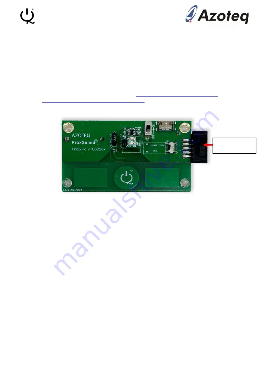
Figure 4.1 Setup for data streaming
Setup the base board connection with a computer by doing the following:
•
Connect the CT210A to a computer via a micro USB cable
•
Connect the base board to the CT210A
•
Insert a module board onto the main board
•
Make sure the slide switch is in the OFF position, the board will run on power from the
CT210A and not on battery power
•
Install the IQS227 and IQS228 GUI on a computer
•
Run the application that matches the chosen module board (IQS227/8)
4.2 Using the GUI with the IQS227B IC
When all of this is done correctly, your screen should look like in Figure 4.2. A small popup Hints &
Tips window also appears which must be read and closed. The important parts to get started with
the GUI are also circled. (We use IQS227 GUI Version 1.0.1.26 in this document and we also
encourage customers to use the latest versions available.)
Connect CT210A
ribbon cable


