10015UK 01 -2004
Technical information:
ES-525 Validator
22
14
Inhibition line 2
15
Inhibition line 1
16
Inhibition line 5
17
Inhibition line 6
1
17
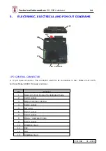
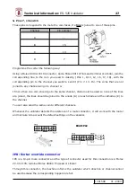
The following is a detailed description of each of the pins on this connector:
Ô
Pin 1
It has two functions depending on whether
binary
or
dedicated
protocol is used (see pin 8).
In
binary
protocol, it reflects the voltage applied to pin nº 3, this way it indicates to the
machine which protocol is being used.
In
dedicated
protocol, it corresponds to coin output 6
Ô
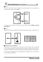
Pins 2, 4, 6, 7 and 9
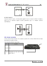
These are the coin output lines and the voltage applied is the same as on pin 3 (see pin 3).
The coin outputs are open circuit, so in the machine that the
validator
is installed they have to
be closed (see Fig.).
b
c
e
Vcoma
ES 525
R
Imax< 50mA
MACHINE
Coin
output
Summary of Contents for ES-525
Page 20: ...10015UK 01 2004 Technical information ES 525 Validator 19 CE...
Page 33: ...10015UK 01 2004 Technical information ES 525 Validator 32 CPU Sel ES525 UK...
Page 34: ...10015UK 01 2004 Technical information ES 525 Validator 33...
Page 40: ...10015UK 01 2004 Technical information ES 525 Validator 39...


