Assembly Instructions
9
Assembly 2
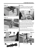
Figure 17
Holding the lathe extension, secure in place using the
3/8” Hex bolts and washers (d)
Figure 15
Remove the tailstock stop “PIN” and place safely aside
Figure 16
Slot the centre pin into the centre hole in the lathe
extension (H)
d
H
1. Line up the holes in the lathe extension (H) with
the threaded holes in lathe stand (F) and secure
using the 3/8” Hex bolts and washers (d), see figure
18.
Figure 18
Using the 3/8” Hex bolts and washers (d),
secure the lathe extension in position
H
2. Release the headstock lock and slide the headstock
down to the end of the lathe bed and lock in position.
Slide the tool rest assembly onto the lathe extension
(H), undo the tool rest locking handle and remove
tool rest. Locate the tool rest extension (I), slot the
tool rest extension into the machined recess and
tighten the clamping handle.
3. Loosen the clamping handles on the tool rest
extension (I) and slot the tool rest into the extension,
tighten the tool rest locking handle. (See figure 19)
Figure 19
d
I
H
Tool rest
Tool rest lock
Tool rest assembly
Summary of Contents for AT1628VS
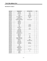
Page 15: ...Parts Breakdown List 15 Headstock Assembly A...
Page 16: ...Parts Breakdown List 16 Headstock Assembly A...
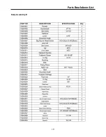
Page 17: ...Parts Breakdown List 17 Headstock Assembly A...
Page 18: ...Parts Breakdown List 18 Body Assembly B...
Page 19: ...Parts Breakdown List 19 Body Assembly B...
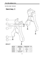
Page 20: ...Parts Breakdown List 20 Stand Assembly C Optional...
Page 21: ...Parts Breakdown List 21...
Page 22: ...Wiring Diagram 22...
Page 23: ...Notes 23...


