background image

Operating Instructions   

13

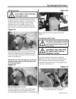
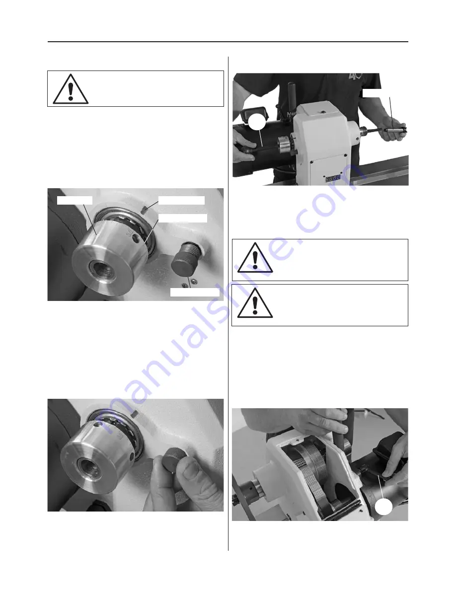
Indexing facility

Removing the Drive Centre

The Indexing ring is situated to the left side of the 
headstock which incorporates 36 positions at (10˚) 
segments. To the side of index ring is the index 
locking pin to lock the spindle in position. The 
indexing facility is useful for fluted columns, clock 
faces and accurate hole positioning. (See figure 23)

Figure 23

Index ring

Index lock pin

10˚ Segments

Index marker

Figure 24

Line up the measurement you require on the index 
ring with the index marker on the headstock and 
screw in the index locking pin to lock the spindle in 
position. (See figure 24) 

NOTE: Make sure the measurement is in line with 
the index marker otherwise the locking pin may 
not in gauge properly.

To remove the drive centre from the spindle, locate 
the push rod (C), insert it through the index ring 
assembly and push the drive centre out, see figure 25.

Figure 25

Drive centre

C

Changing the belt speed

Note: The lowest speed pulley combination 
is furthest from the faceplate, the smallest 
motor pulley diameter to largest spindle 
pulley diameter.

DISCONNECT THE LATHE FROM 
THE MAINS SUPPLY BEFORE 
CHANGING THE BELT 

DISCONNECT THE LATHE FROM 
THE MAINS SUPPLY 

Open up the pulley access panel on top of the 
headstock by removing the Hex screw. Slacken the 
belt by loosening the motor locking handle (a)
move the motor until the belt is slack enough to be 
reposition.  (See figure 26)

Figure 26

Loosen the motor locking handle (a) enough  

to allow the pulley to be repositioned

a

Continues Over...

Repeat the procedure for the live centre in the 
tailstock.

Summary of Contents for AT1628VS

Page 1: ...Axminster Tool Centre Unit 10 Weycroft Avenue Axminster Devon EX13 5PH www axminster co uk AT1628VS Variable Speed Wood Lathe Code 502703...

Page 2: ...declares that the machine described hereafter WOOD TURNING LATHE manufactured byKingcraft Machinery Company Limited is in compliance with the standards determined in the following Council Directive EN...

Page 3: ...ck Pin D 1 No Motor Plate Handle E 1 No Instruction Manual Quantity Item Part Code Number 1 No Lathe Extension H 502704 4 No 3 8 x 1 3 4 Hex Bolts 8 No 3 8 Washers 1 No Tool Rest Extension I 2 No Lath...

Page 4: ...machine with a damp soapy cloth if needs be do not use any solvents or cleaners as these may cause damage to any plastic parts or to the electrical components Clean the machine components with a light...

Page 5: ...ar of the tool rest not split or has loose knots 6 Where lathes have the facility to be reversed check the machine is rotating in the correct direction 7 If your lathe has the facility to run in rever...

Page 6: ...able to use a lifting device such as a hoist scissor lift or seek help when assembling the lathe The majority of the machine comes fully assembled the remaining items to be assembled is described belo...

Page 7: ...allet onto a work bench see figs 7 then refit the headstock tool rest and tailstock as described in steps 1 and 2 see figure 8 Figure 07 Figure 08 1 Locate the two lathe stands F and the four feet G S...

Page 8: ...ample to raise the lathe bed to mount the lathe stands Figure 14 c c Lathe Extension Assembly Code 502704 Assembly 1 The lathe extension H bolts onto either end of the lathe bed which increases the le...

Page 9: ...Using the 3 8 Hex bolts and washers d secure the lathe extension in position H 2 Release the headstock lock and slide the headstock down to the end of the lathe bed and lock in position Slide the too...

Page 10: ...wheel Motor plate handle Tailstock barrel lock Tailstock lock Tailstock lock stop Headstock Motor locking handle Faceplate Spindle speed LED Live centre Lathe bed Tool rest lock Control box Headstock...

Page 11: ...tons ON OFF Forward and Reverse switch The Speed Control Knob enables you to increase or decrease the speed of the spindle Headstock Pivot Lock pull this knob to rotate the headstock to the desired po...

Page 12: ...allow bowls to be turned in front of the lathe See figures 19 20 Figure 18 Lift up the Headstock locking handle a pull the Headstock pivot lock b out and swivel the Headstock to the desired position F...

Page 13: ...erwise the locking pin may not in gauge properly To remove the drive centre from the spindle locate the push rod C insert it through the index ring assembly and push the drive centre out see figure 25...

Page 14: ...shavings away from the lathe bed and tool rest Smear a light coat of wax Protec Tool Wax Polish Code 211835 over the lathe bed to allow the Banjo and Tailstock to run smoothly over the lathe bed and...

Page 15: ...Parts Breakdown List 15 Headstock Assembly A...

Page 16: ...Parts Breakdown List 16 Headstock Assembly A...

Page 17: ...Parts Breakdown List 17 Headstock Assembly A...

Page 18: ...Parts Breakdown List 18 Body Assembly B...

Page 19: ...Parts Breakdown List 19 Body Assembly B...

Page 20: ...Parts Breakdown List 20 Stand Assembly C Optional...

Page 21: ...Parts Breakdown List 21...

Page 22: ...Wiring Diagram 22...

Page 23: ...Notes 23...

Page 24: ...te recycling bin Do not dispose of electric tools together with household waste material In observance of European Directive 2002 96 EC on waste electrical and electronic equipment and its implementat...

Reviews: