


Assembly/Setup
6
The AT2600BS Belt Sander comes fully assembled apart from
the end table (B) and the guard (C) assembly. Follow the
instructions below for assembly.
Locate the guard (C) and the two locking knobs and washers.
Lower the guard onto the end table (B), line up the mounting
holes with the threaded holes in the table’s casting and secure
in place with the locking knobs/washers, see fig 3.
Remove the shipping crate lid and side panels and place safely
aside. BE CAREFUL when removing the panels as exposed nails
can course injury.
Loosen the two cap head screws (a) on either side of the
machine’s mounting bracket , see fig 1. Slide the end table (B),
mounting bar between the bracket and line up the machined
holes with the cap head screws and secure in place. Nip-up the
locking nuts (b) to prevent the table from moving, see fig 2.
Place a 90˚ square on the table and check it’s perpendicular
with the sanding belt. If adjustment is required, loosen the two
locking nuts (b) and adjust the table’s pivoting bolts (c) until
correct. Nip-up the locking nuts (b).
1
2
4
3
a
b
Pivoting bolts
Mounting bar
Lock nut
180kg
THE MACHINE IS HEAVY YOU WILL
REQUIRE ASSISTANCE TO MOVE IT!
REMOVE ALL PACKAGING
AND RECYCLE!
C
Mounting
bracket
Locking knob
Positioning the Machine
Setting the Work Tables
Ascertain the orientation and with assistance manoeuvre the
machine to required position making sure the floor is level and
there is sufficient space all round. Lift the sander off the pallet
and place carefully on the floor, see fig 4. The sander’s base has
four pre-drilled holes to bolt the sander securely down.
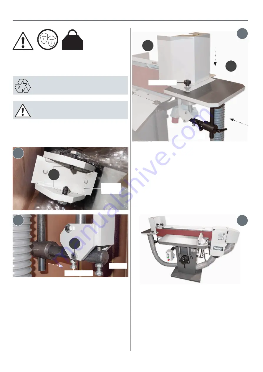
Main Table
The main table can be raised or lowered to the required
position. Firstly loosening the locking handle on the rise & fall
control unit, see fig 5. Turn the operating wheel clockwise to
raise or anti-clockwise to lower, see fig 6. Secure the locking
handle.
B


