


AXIS Q8414–LVS Network Camera
LED Indicators
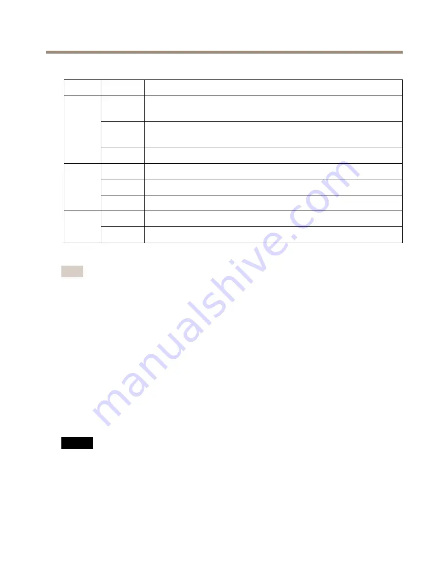
LED
Color
Indication
Green
Steady for connection to a 100 Mbit/s network. Flashes for network
activity.
Amber
Steady for connection to a 10 Mbit/s network. Flashes for network
activity.
Net-
work
Unlit
No network connection.
Green
Steady green for normal operation.
Amber
Steady during startup and when restoring settings.
Status
Red
Slow flash for failed upgrade.
Green
Normal operation.
Power
Amber
Flashes green/amber during firmware upgrade.
Note
• The Status LED can be configured to be unlit during normal operation. To configure, go
to
Setup > System Options > Ports & Devices > LED
. See the online help for more
information.
• The Status LED can be configured to flash while an event is active.
• The Status LED can be configured to flash for identifying the unit. Go to
Setup > System
Options > Maintenance
.
Connectors and Buttons
For specifications and operating conditions, see
page 13
.
Network Connector
RJ45 Ethernet connector with Power over Ethernet (PoE).
NO
NO
NOTICE
TICE
TICE
The product shall be connected using a shielded network cable (STP). All cables connecting
the product to the network shall be intended for their specific use. Make sure that the
network devices are installed in accordance with the manufacturer’s instructions. For
information about regulatory requirements, see
Electromagnetic Compatibility (EMC) on
page 2
.
11
Summary of Contents for Q8414-LVS
Page 1: ...AXIS Q8414 LVS Network Camera Installation Guide...
Page 4: ......
Page 8: ...8...
Page 27: ...27...