18
4.7. Panic Button (Optional)
Overview
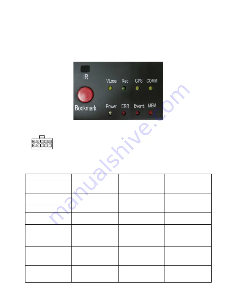
The LEDs are used to show the device’s working status. But when the device is installed in
the vehicle, it is not easy to check the LED on the front panel. Each of the LED indicates the
corresponding status. Furthermore, the panic button on the panel make it easier to trigger alarm for
emergency or bookmarking a manual event.
Pin Definition
2*5 PIN/3.0 interface connect to the interface on panic button.
LED
LED
Color
ON
OFF
VLoss
Amber
Any of the cameras
have no signal alarm
Normal Operation
Rec
Soft green
Recording Normal
driving
Not recording
GPS
Amber
GPS cannot latch
Normal Operation
Mem
Red
Storage Alarm or no
Storage device
Normal Operation
Comm
Amber
Device is not
connected to server
Normal operation
or device is not
connected to server if
this feature is disabled
Power
Pale Blue
Device has power
Device does not have
power
Error
Red
Error with device
Normal Operation
Event
Red
Event-based
Recording (remains lit
during Event)
Normal Operation
Summary of Contents for DV425
Page 25: ...25 5 7 Volume Modulation 0 is the minimum volume and 10 is the maximum volume 6 Record Setup ...
Page 37: ...37 7 9 Mirror ON Turn on Mirror function OFF Turn off Mirror function 8 Network ...
Page 43: ...43 8 5 FTP ...
Page 44: ...44 9 System 9 1 Log in Setup Set user name and password for boot up ...
Page 45: ...45 9 2 License Plate Number Setup Set license plate number and IP number ...
Page 47: ...47 9 5 Exception 9 6 ACC Settings ...
Page 55: ...55 9 10 System Info System Info Software version number ...
Page 58: ...58 12 NOTES ...
Page 59: ...59 ...
Page 60: ...60 DV425 DV425GPS ...


