rBOX101-FL Series User’s Manual
Introduction
73
z
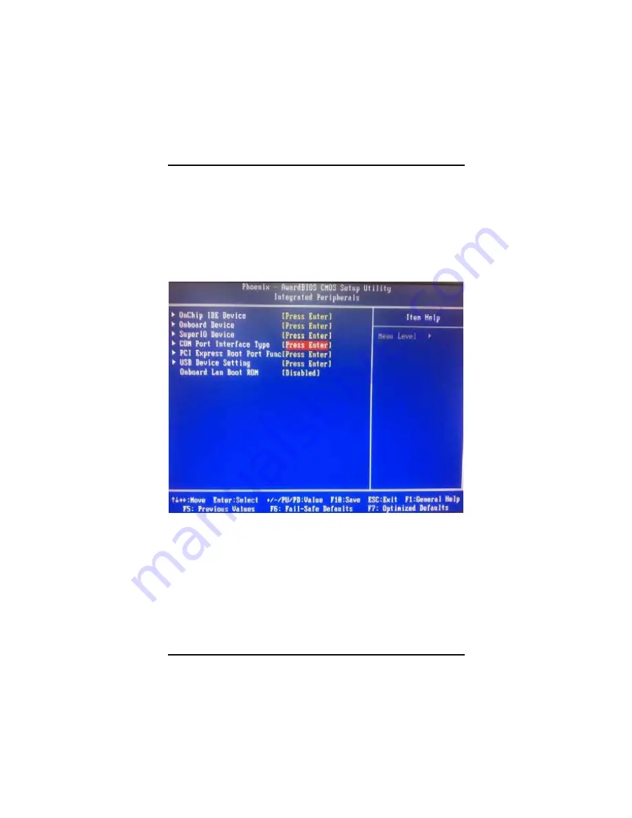
COM Port Interface Type
¾
COM Port 1~6 (for rBOX101-6COM),
¾
COM Port 1~4 (for rBOX101-4COM)
The default setting for all COM Ports are RS232, you can change the
default setting by selecting the value you want in each COM Port
Type.
Press <ESC> to return to the Integrated Peripherals page
.
Summary of Contents for rBOX101-FL Series
Page 1: ...rBOX101 FL Series Robust Din rail Fanless Embedded System User s Manual...
Page 9: ...ix MEMO...
Page 10: ......
Page 19: ...rBOX101 FL Series User s Manual Introduction 9 Reference 1 Digital Input Connectivity...
Page 20: ...rBOX101 FL Series User s Manual Introduction 10 Reference 2 Digital Output Connectivity...
Page 24: ...rBOX101 FL Series User s Manual Introduction 14 Below pictures are the LED example...
Page 25: ...rBOX101 FL Series User s Manual Introduction 15...
Page 26: ...rBOX101 FL Series User s Manual Introduction 16...
Page 27: ...rBOX101 FL Series User s Manual Introduction 17...
Page 31: ...rBOX101 FL Series User s Manual Introduction 21 rRBOX101 4COM FL...
Page 33: ...rBOX101 FL Series User s Manual Introduction 23 rBOX101 4COM LAN 1 2 USB LED COM 1 4...
Page 38: ...rBOX101 FL Series User s Manual Introduction 28...
Page 42: ...rBOX101 FL Series User s Manual Introduction 32 Step 3 Locate the CompactFlash TM socket...
Page 51: ...rBOX101 FL Series User s Manual Introduction 41 NOTE The Din rail kit drawing is listed below...
Page 54: ...rBOX101 FL Series User s Manual Introduction 44...
Page 58: ...rBOX101 FL Series User s Manual Introduction 48...
Page 78: ...rBOX101 FL Series User s Manual Introduction 68...
Page 84: ...rBOX101 FL Series User s Manual Introduction 74...
Page 89: ...rBOX101 FL Series User s Manual Introduction 79...
Page 96: ...rBOX101 FL Series User s Manual Introduction 86...
Page 112: ...rBOX101 FL Series User s Manual Installation of Drivers 102 MEMO...


