MPC152-832
User’s Manual
Hardware and Installation
11
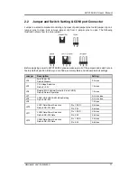
2.2 Jumper and Switch Setting & COM port Connector
Jumper is a small component consisting of jumper clip and jumper pins. Install jumper clip on 2
jumper pins to close. And remove jumper clip from 2 jumper pins to open. The following
illustration shows how to set up jumper.
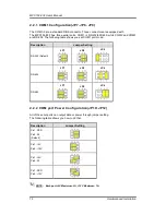
Before applying power to MPC152-832, please make sure all of the jumpers and switch are in
factory default position. Below you can find a summary table and onboard default settings.
Jumper
Description
Setting
JP4
Auto Power On
Default: Disable
2-3 close
JP5
CF Voltage Selection
Default: +3.3V
1-2 close
JP6
Restore BIOS Optimal Defaults (Clear CMOS)
Default: Normal Operation
1-2 close
JP7
COM1 RS-232/422/485 Mode Setting
Default: RS-232
3-5, 4-6 close
JP8
3-5, 4-6 close
JP9
1-2 close
JP10
COM1 Data/Power Selection
Default: RS-232 Data
Pin 1: DCD
3-5 close
Pin 9: RI
4-6 close
JP11
COM2 Data/Power Selection
Default: RS-232 Data
Pin 1: DCD
3-5 close
Pin 9: RI
4-6 close
JP12
COM3 Data/Power Selection
Default: RS-232 Data
Pin 1: DCD
3-5 close
Pin 9: RI
4-6 close


