background image

eBOX700-891-FL Series u

ser’s Manual 


Hardware Installation 

19 

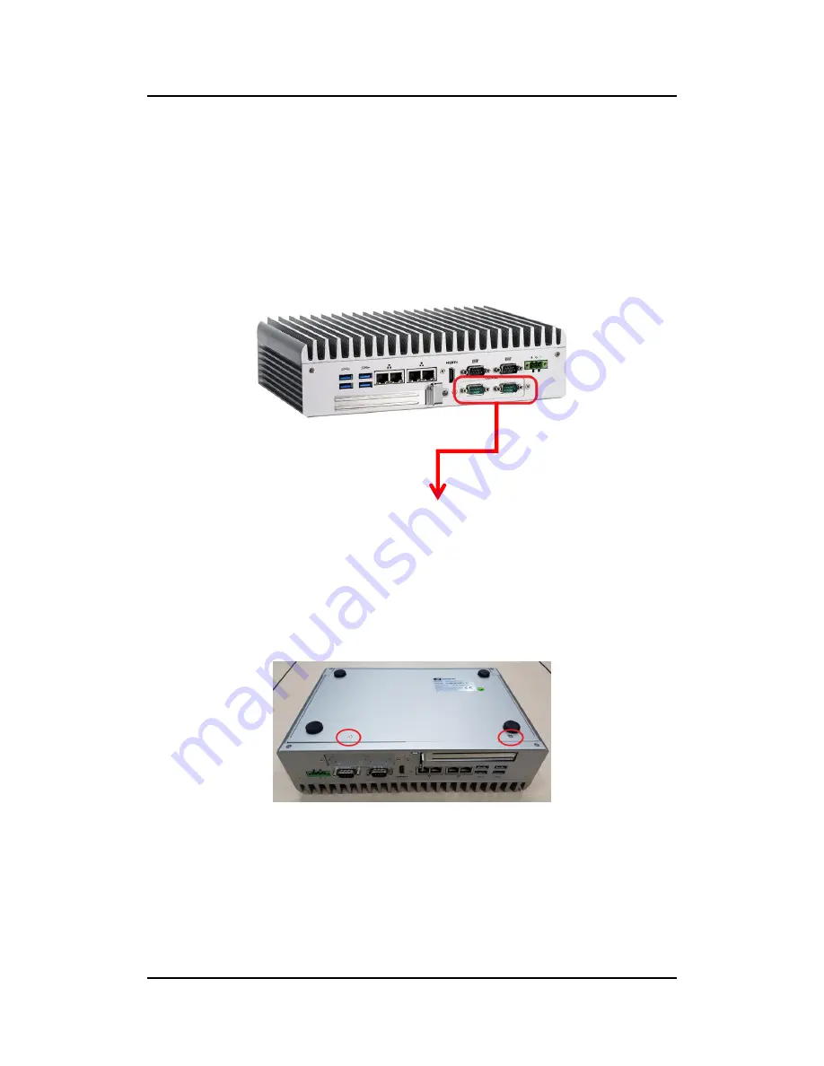
2.5     Installation of Flexible I/O Modules 

The  eBOX670-891  provides  an  optional  window  for  custom er  add  flexible  I/O 
modules, according to different modules , please re  follow the below 

Instructions:


-AX92902 LAN Module (RJ45 connector*1) 

-AX92904 DIO Module (DB44 connector*1) 

-AX92903 CAN Bus/CAN Open Module (DB9 connector*1) 

-AX92906 COM Module (DB9 connector*2) 


Step 1  Prepare the flexible IO module (ex: CAN Bus module kit). 

Step 2  Turn off the system. 

Step 3  Open the bottom cover.  


Optional I/O Door 

(Default: 2 x DB9 half cut bracket) 

Flexible IO window 

(Default: 2 x DB9 half cut bracket) 

Summary of Contents for eBOX700-891-FL Series

Page 1: ...eBOX700 891 FL Series Embedded System User s Manual...

Page 2: ...usefulness of any information in this document Axiomtek does not make any commitment to update any information in this manual Axiomtek reserves the right to change or revise this document and or prod...

Page 3: ...Make sure the voltage of the power source is correct before connecting it to any power outlet 5 Turn Off system power before cleaning Clean the system using a cloth only Do not spray any liquid clean...

Page 4: ...n against electric shock not classified 2 Degree of protection against ingress of water IP40 3 Equipment not suitable for use in the presence of a flammable anesthetic mixture with air oxygen or nitro...

Page 5: ...tention to components requiring designated products for cleaning as mentioned below Cloth A piece of cloth is the best tool to use when rubbing up a component Although paper towels or tissues can be u...

Page 6: ...tek is a trademark of Axiomtek Co Ltd IBM PC AT PS 2 VGA are trademarks of International Business Machines Corporation Intel and Pentium are registered trademarks of Intel Corporation MS DOS Microsoft...

Page 7: ...ation of 2 5 SATA Device 14 2 3 Installation of SO DIMM 16 2 4 Installation of PCIe card 17 2 5 Installation of Flexible I O Modules 19 2 6 Installation of USB Dongle kit 22 SECTION 3 JUMPER CONNECTOR...

Page 8: ...e PCI Express Mini Card Slot SCN2 SCN3 33 3 3 17 PCI Express x4 slot PCIE1 35 SECTION 4 BIOS SETUP UTILITY 37 4 1 Starting 37 4 2 Navigation Keys 37 4 3 Main Menu 38 4 4 Advanced Menu 39 4 5 Chipset M...

Page 9: ...exible I O design To fulfill different application needs the flexible embedded system supports Windows 10 and Linux and it can be wall mounted and Din rail mounted by optional requests The eBOX700 891...

Page 10: ...ution for industrial field applications and motion vision markets Flexible Connectivity It comes with rich I O interfaces including two RS 232 ports four USB 3 0 ports two USB 2 0 ports four GbE LAN p...

Page 11: ...ess Mini Card Slots USB PCI Express signal 1 x full size PCI Express Mini Card Slots USB SATA signal Expansion Slot 1 x PCIe x4 Note Supports dimensions of standard half size PCIE card Max up 167 65mm...

Page 12: ...SSD Memory Humidity 10 95 non condensation Vibration Endurance 3Grm with SSD 5 500Hz X Y Z directions Weight 3 8 kg 8 37 lb without package 4 6 kg 10 14 lb with package Dimension 280 mm 11 02 W x 190...

Page 13: ...eBOX700 891 FL Series user s Manual Introduction 5 1 3 Dimensions The following diagrams show dimensions and outlines of the eBOX700 891 FL 1 3 1 System Dimensions...

Page 14: ...eBOX700 891 FL Series user s Manual Introduction 6 1 3 2 Wall mount Bracket Dimensions...

Page 15: ...eBOX700 891 FL Series user s Manual Introduction 7 1 3 3 Din rail Bracket Dimensions...

Page 16: ...00 891 FL Front View Rear View 1 Reset switch 7 DisplayPort 13 Phoenix connector 9 36VDC 2 ATX AT Quick switch 8 HDMI 1 4 14 4 x GbE LANs 3 ATX Power switch 9 2 x USB 2 0 15 HDMI 2 0 4 4 x Programmer...

Page 17: ...ermal Pad x 2 PCH Thermal Pad x 1 HDD screws x 2 Terminal Block x 1 Remote switch cable x 1 HDD Bracket x 1 1 6 Model List eBOX670 891 FL DC Flexible IO Fanless Embedded System with LGA1151 Socket 6th...

Page 18: ...eBOX700 891 FL Series user s Manual Introduction 10 This page is intentionally left blank...

Page 19: ...s guidelines for hardware installation 2 1 Installation of CPU Step 1 Turn off the system Step 2 Loosen all screws to remove top cover Step 3 Remove the warning label and disengage load lever Disengag...

Page 20: ...sor which aligns with connection 1 indicator chamfer on the socket and notice processor keying features that line up with posts along socket walls Grasp the processor with thumb and index finger along...

Page 21: ...s of the socket Be careful of the CPU s orientation that user s need to align the arrow mark on the CPU with the arrow key on the socket Step 6 Paste the thermal pad on top of the processor with cauti...

Page 22: ...tion of 2 5 SATA Device Step 1 Turn off the system Step 2 Turn the system upside down to locate screws at the bottom and then loosen all screws Step 3 Open the bottom cover Step 4 Locate SSD HDD withi...

Page 23: ...the SSD HDD please prepare HDD bracket HDD screws and then assemble the SSD HDD with the HDD mounting screws Make sure the PCB side of the SSD HDD will be facing the bottom cover Step 6 Connected the...

Page 24: ...ur screws on the top heatsink are used to fasten the heatsink to the chassis Step 3 Located the dual SO DIMM sockets on main board Step 4 Locate the memory module insert a gold colored contact into th...

Page 25: ...ation of PCIe card Step 1 Turn off the system Step 2 Turn the system upside down to locate screws at the bottom and then loosen all screws Step 3 Identify the location of the PCIe slot as below red ma...

Page 26: ...L Series user s Manual Hardware Installation 18 Step 5 Insert the PCIe card and fasten the screw of PCIe card adjustable bracket Step 6 Fasten the small bracket screw and put the bottom cover back ont...

Page 27: ...ding to different modules please re follow the below Instructions AX92902 LAN Module RJ45 connector 1 AX92904 DIO Module DB44 connector 1 AX92903 CAN Bus CAN Open Module DB9 connector 1 AX92906 COM Mo...

Page 28: ...are Installation 20 Step 4 Loosen the two screws of flexible IO door and push the hole which is not punched through Step 5 Insert the CAN Bus mini PCIe card One mini card with one DB 9 connector Step...

Page 29: ...s Manual Hardware Installation 21 Step 7 Fasten the CAN Bus connector with bracket onto the chassis and then connect the CAN Bus cable to the mini PCIe card Step 8 Put the bottom cover and fasten two...

Page 30: ...provides an adjustable USB dongle bracket for customer use Step 1 Turn off the system Step 2 Turn the system upside down to locate screws at the bottom and then loosen all screws Step 3 Locate USB do...

Page 31: ...CTION 3 JUMPER CONNECTOR SETTINGS Proper jumper settings configure the eBOX700 891 FL to meet various application needs Hereby all jumpers settings along with their default settings are listed for dev...

Page 32: ...r Connector Settings 24 SBC87891 Bottom View Note It is strongly recommended that any unmentioned jumper settings should not be modified without instructions by Axiomtek FAEs Any modifications without...

Page 33: ...s Descriptions Settings JP1 Restore BIOS Optimal Defaults Default Normal Operation Short 1 2 Note How to setup Jumpers That a cap on a jumper is to close the jumper whereas that offs a jumper is to op...

Page 34: ...r 3 3 3 Serial Port Connector 3 3 4 USB 3 0 Connector 3 3 5 Ethernet Connector 3 3 6 USB 2 0 Connector 3 3 7 Audio Connector 3 3 8 ATX Power On Off Button 3 3 9 Rest Button 3 3 10 Remote Power Switch...

Page 35: ...High Definition Multimedia Interface is a compact digital interface which is capable of transmitting high definition video and high resolution audio over a single cable Pins Signals Pins Signals HDMI2...

Page 36: ...E3 20 3 3V 3 3 4 Serial Port Connector CN18 CN19 The system has two serial ports COM1 COM2 are RS 232 422 485 ports Please refer to Chapter 4 for the detail of BIOS setting COM1 CN18 COM2 CN19 Pins RS...

Page 37: ...USB_Data 11 USB_Data 3 USB_Data 12 USB_Data 4 GND 13 GND 5 SSRX 14 SSRX 6 SSRX 15 SSRX 7 GND 16 GND 8 SSTX 17 SSTX 9 SSTX 18 SSTX 3 3 6 Ethernet Connector CN12 CN13 The board has four RJ 45 connectors...

Page 38: ...re compliant with USB 2 0 480Mbps and ideally for installing USB peripherals such as keyboard mouse scanner etc 3 3 8 Audio Connector CN1 CN2 These two audio jacks ideal are for Audio Mic In and Audio...

Page 39: ...ton can allow users to reset eBOX700 891 FL Functions Descriptions On Reset system Off Keep system status 3 3 11 Remote Power Switch Connector PWRBT1 One 2 pin connector output for remote power on off...

Page 40: ...s two SATA 3 0 ports with 6Gb s performance 3 3 14 SATA Power Connector CN8 Use CN8 for interfacing to SATA 2 5 HDD power supply 3 3 15 SIM Card Slots SCN1 The eBOX700 891 FL includes one SIM slots SC...

Page 41: ...rds into this slot Please refer to the SATA of BIOS setting to enable or disable mSATA supported SCN2 Pins Signals Pins Signals 1 WAKE 2 3 3VSB 3 No use 4 GND 5 No use 6 1 5V 7 CLKREQ 8 No use 9 GND 1...

Page 42: ...use 15 GND 16 No use 17 No use 18 GND 19 No use 20 W_DISABLE 21 GND 22 PERST 23 PE_RXN3 mSATA SATA_RXP 24 3 3VSB 25 PE_RXP3 mSATA SATA_RXN 26 GND 27 GND 28 1 5V 29 GND 30 SMB_CLK 31 PE_TXN3 mSATA SAT...

Page 43: ..._PS B11 PCH_WAKE_N A11 PWRGD B12 N C A12 GND B13 GND A13 CLKOUT_PCIE_P5 B14 PCIE1_SLOT1_TX_DP_C A14 CLKOUT_PCIE_N5 B15 PCIE1_SLOT1_TX_DN_C A15 GND B16 GND A16 PCIE1_SLOT1_RX_DP_C B17 PCIEX4_SLOT1_PRSN...

Page 44: ...eBOX700 891 FL Series user s Manual Jumper Connector Settings 36 This page is intentionally left blank...

Page 45: ...etup navigation process These keys include F1 F2 Enter ESC Arrow keys and so on Note Some of the navigation keys differ from one screen to another Hot Keys Descriptions Left Right The Left and Right A...

Page 46: ...screen is also shown below BIOS Information Display the auto detected BIOS information System Language Choose the system default language System Date Time Use this option to change the system time an...

Page 47: ...the CPU and other system devices Users can select any items in the left frame of the screen to go to sub menus ACPI Settings CPU Configurations SATA Configurations PCH FW Configurations NCT6102D Super...

Page 48: ...o select options for the ACPI configuration and change the value of the selected option A description of the selected item appears on the right side of the screen ACPI Sleep State When the sleep butto...

Page 49: ...ions This screen shows the CPU version and its detailed information Hyper Threading Enable or disable Hyper threading Technology which allows a single physical processor to multitask as multiple logic...

Page 50: ...r s Manual BIOS Setup Utility 42 SATA Configurations In this Configuration menu you can see the currently installed hardware in the SATA ports During system boot up the BIOS automatically detects the...

Page 51: ...eBOX700 891 FL Series user s Manual BIOS Setup Utility 43 PCH FW Configuration This screen shows ME Firmware information...

Page 52: ...r IO Configurations Use this screen to select options for the NCT6102D Super IO Configurations and change the value of the selected option A description of the selected item appears on the right side...

Page 53: ...eBOX700 891 FL Series user s Manual BIOS Setup Utility 45 Serial Port 1 2 COM1 2 Configurations Use these items to set parameters related to serial ports 1 2...

Page 54: ...eBOX700 891 FL Series user s Manual BIOS Setup Utility 46 Serial Port 2...

Page 55: ...0 891 FL Series user s Manual BIOS Setup Utility 47 Hardware Monitor This screen monitors hardware health status This screen displays the temperature of system and CPU system voltages VCORE 3 3V 12V a...

Page 56: ...eBOX700 891 FL Series user s Manual BIOS Setup Utility 48 USB Configurations USB Devices Display all detected USB devices...

Page 57: ...eBOX700 891 FL Series user s Manual BIOS Setup Utility 49 Utility Configurations This screen is for BIOS flash utility BIOS Flash Utility BIOS flash utility configuration...

Page 58: ...nu The Chipset menu allows users to change the advanced chipset settings Users can select any of the items in the left frame of the screen to go to the sub menus System Agent SA Configurations PCH IO...

Page 59: ...Manual BIOS Setup Utility 51 System Agent SA Configurations Graphics Configuration Use this item to configure internal graphics controller Memory Configuration Use this item to refer to the informati...

Page 60: ...eBOX700 891 FL Series user s Manual BIOS Setup Utility 52 Graphic Configurations...

Page 61: ...eBOX700 891 FL Series user s Manual BIOS Setup Utility 53 Memory Configurations This screen shows the system memory information...

Page 62: ...eBOX700 891 FL Series user s Manual BIOS Setup Utility 54 PCH IO Configurations This screen allows users to set PCH parameters...

Page 63: ...Setup Utility 55 Security Menu Administrator Password This item indicates whether an administrator password has been set installed or uninstalled User Password This item indicates whether a user passw...

Page 64: ...indefinite waiting Bootup NumLock State Use this item to select the power on state for the keyboard NumLock Quiet Boot Select to display either POST output messages or a splash screen during boot up L...

Page 65: ...hanges to the system configurations and return to Main Menu Select Discard Changes and Exit from the Save Exit menu and press Enter Select Yes to discard changes and exit Save Changes and Reset When c...

Page 66: ...re Defaults It automatically sets all Setup options to a complete set of default settings when users select this option Select Restore Defaults from the Save Exit menu and press Enter Save as User Def...

Page 67: ...someone to reboot when computer hangs The systems need to be able to reset automatically when things go wrong The watchdog timer gives us solutions in this regard The watchdog timer is a counter that...

Page 68: ...ion O 2E 87 Un lock super I O O 2E 87 Select logic device O 2E 07 O 2F 08 WDT device enable O 2E 30 O 2F 01 Set timer unit O 2E F0 O 2F 00 00 Sec 08 Minute Set base timer O 2E F1 O 2F 0A Set reset tim...

Page 69: ...le LED 61 APPENDIX B PROGRAMMABLE LED About Programmable LED eBOX700 891 FL supports four programmable LED which allows user to program the LED status It can do as special indicator or alarm Please re...

Page 70: ...eBOX700 891 FL Series user s Manual Programmable LED 62 This page is intentionally left blank...

Reviews: