Version 2.0.3 Preliminary Documentation – May be Subject to Change 35-36
General Specifications
Microprocessor
DSP56F8346
Control Logic
Standard embedded software is provided.
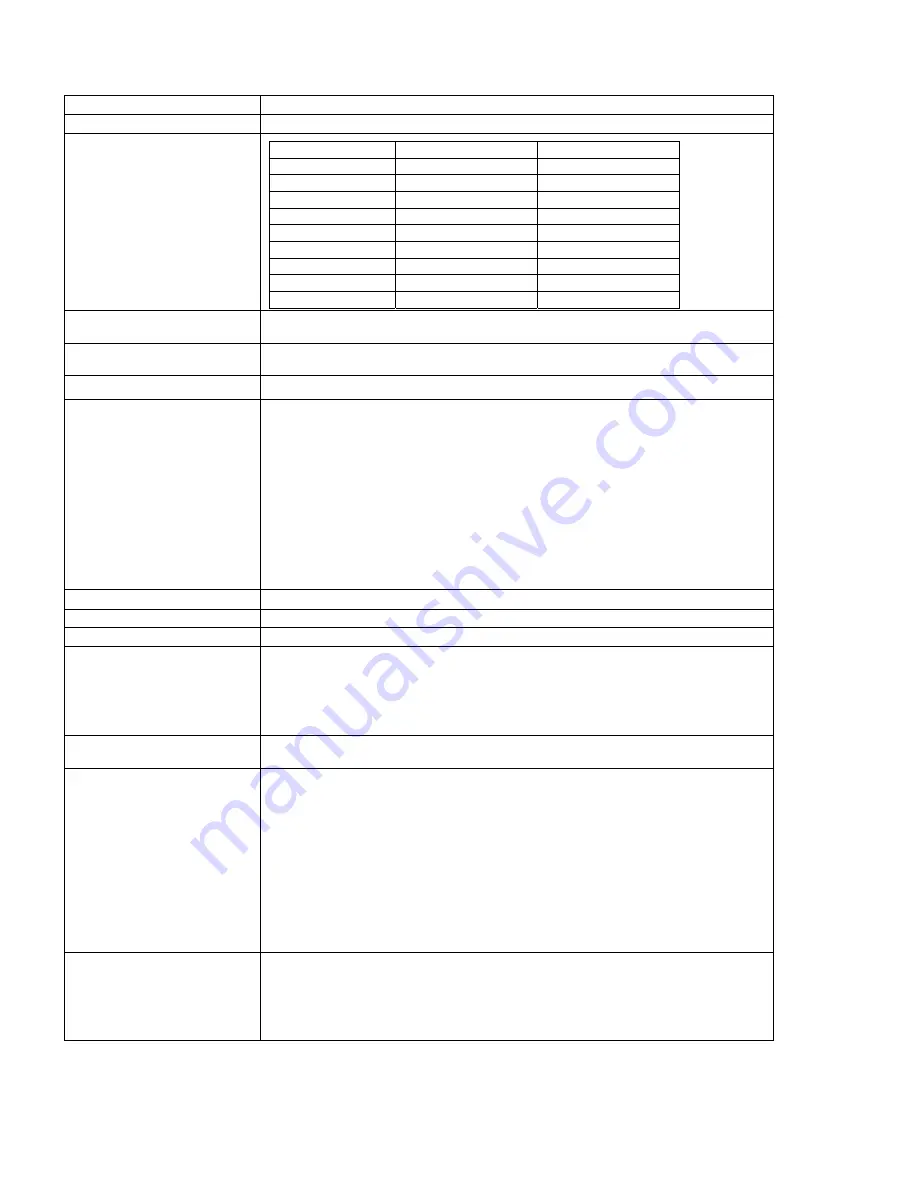
Quiescent Current Draw
BATT+ Voltage (V)
Quiescent Current (ma)
Power - Watts (W)
9 269.8
2.43
10 241.8 2.42
11 220.3 2.42
12 200.5 2.41
15 159.3 2.39
20 115.1 2.30
24 95.9 2.30
28 82.4 2.31
32 72.4 2.32
Communications
1 CAN port (SAE J1939)
1 RS-232
User Interface
Electronic Assistant® for
Windows
operating systems
It comes with a royalty-free license for use.
CAN Interface
1 CAN port (SAE J1939)
Diagnostics
Each input channel can be configured to send diagnostic messages to the network if the
input goes out of range, as described below. In addition to the input channels, three other
types of faults can be reported to the network using diagnostic messaging. They are Over
Temperature (of the controller processor), Over Voltage and Under Voltage (of the power
supply voltage). For each fault condition, there are two setpoints, one that will cause the fault
condition to trigger, and the other that will clear the fault. Even if diagnostic messaging is not
enabled, the Minimum and Maximum Error setpoints can be used to flag an error using the
Axiomatic Proprietary B scheme.
Note: If the Input Sensor Type setpoint is set to either 16-bit Counter or Digital, diagnostics
are not permitted for that channel. Otherwise, whether or not faults will be detected for an
input channel is dependent on the settings of the “Minimum Error” and “Maximum Error”
setpoints.
If these are set to the limits of the range (i.e. 0V or 5V), then fault detection is not
possible.
Operating Conditions
-40 to 85
°
C (-40 to 185
°
F)
Protection
IP65, Unit is conformal coated in the housing.
Weight
2.30 lbs. (1.04 kg)
Electrical Connections
8-pin Deutsch IPD P/N: DT13-08PA
Mating plug p/n: DT06-08SA with wedge W8S and sockets 0462-201-16141
40-pin Deutsch IPD p/n: DRC13-40PA
Mating plug p/n: DRC16-40SA or DRC18-40SA with sockets 0462-201-16141
For pinout, refer to Section 1.6.
Packaging and Dimensions
Aluminum extrusion with stainless steel end plates.
For dimensions, refer to Section 1.6.
Grounding
Protective Earth (PE) must be connected to the grounding stud to reduce the risk of electric
shock. The conductor providing the connection should have a ring lug and wire larger than
or equal to 4 mm
2
(12 AWG). The ring lug should be placed between the nut and a star
washer. (To secure the ground strap, use an 8-32 “K-LOK” locknut, stainless steel, 3/8”
O.D.)
All chassis grounding should go to a single ground point designated for the machine and all
related equipment.
The ground strap that provides a low impedance path for EMI should be a ½ inch wide, flat,
hollow braid, no more than 12 inches long with a suitable sized ring lug for the module’s
grounding lug. It may be used in place of the PE grounding conductor and would then
perform both PE and EMI grounding functions.
Shielding
The CAN wiring should be shielded using a twisted conductor pair. All wire shields should
be terminated externally to the grounding lug on the mounting foot. The input wires should
not be exposed for more than 2 inches (50 mm) without shielding. Shields can be ac
grounded at one end and hard grounded at the opposite end to improve shielding. If the
module is installed in a cabinet, shielded wiring can be terminated at the cabinet (earth
ground), at the entry to the cabinet or at the module.


