12
3)
When RS232 output is active, the auto Power off function is disabled.
3.2.
Measurement Functions
3.2.1.
AC and DC Voltage measurement.
AC Voltage
DC Voltage
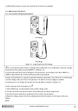
Figure 3-1 measuring AC and DC Voltage
To avoid electrical shock and/or damage to the instrument, do not attempt to take any voltage
measurement that might exceeds 1000Vdc or 1000Vac rms.
To avoid electrical shock and/or damage to the instrument, do not apply more than 1000Vdc or
1000Vac rms between the common terminal and the earth ground
Voltage is the difference in electrical potential between two points. The polarity of ac (alternating
current) voltage varies over time; the polarity of dc (direct current) voltage is constant.
To measure ac or dc voltage (set up and connect the Meter as shown in Figure 3-1):
Set the rotary switch to the position of
V
1)
Press SELECT key to select between AC and DC voltage mode.
2)
Connect the black and red test leads to the COM and V terminals respectively.
3)
Connect the test leads tip in parallel with the circuit to be measured.
4)
Read the voltage value on the main-display and read the frequency of AC signal on the sub-
display.
NOTE:


