axing MIE 4-02 Operation Instructions Manual Download Page 107

Operation instructions | MIE 4-02 | MIE 8-02

46

2020-11-13 | Technical improvements, changes in design, printing- and other errors expected.

3.7.2.

Load license file

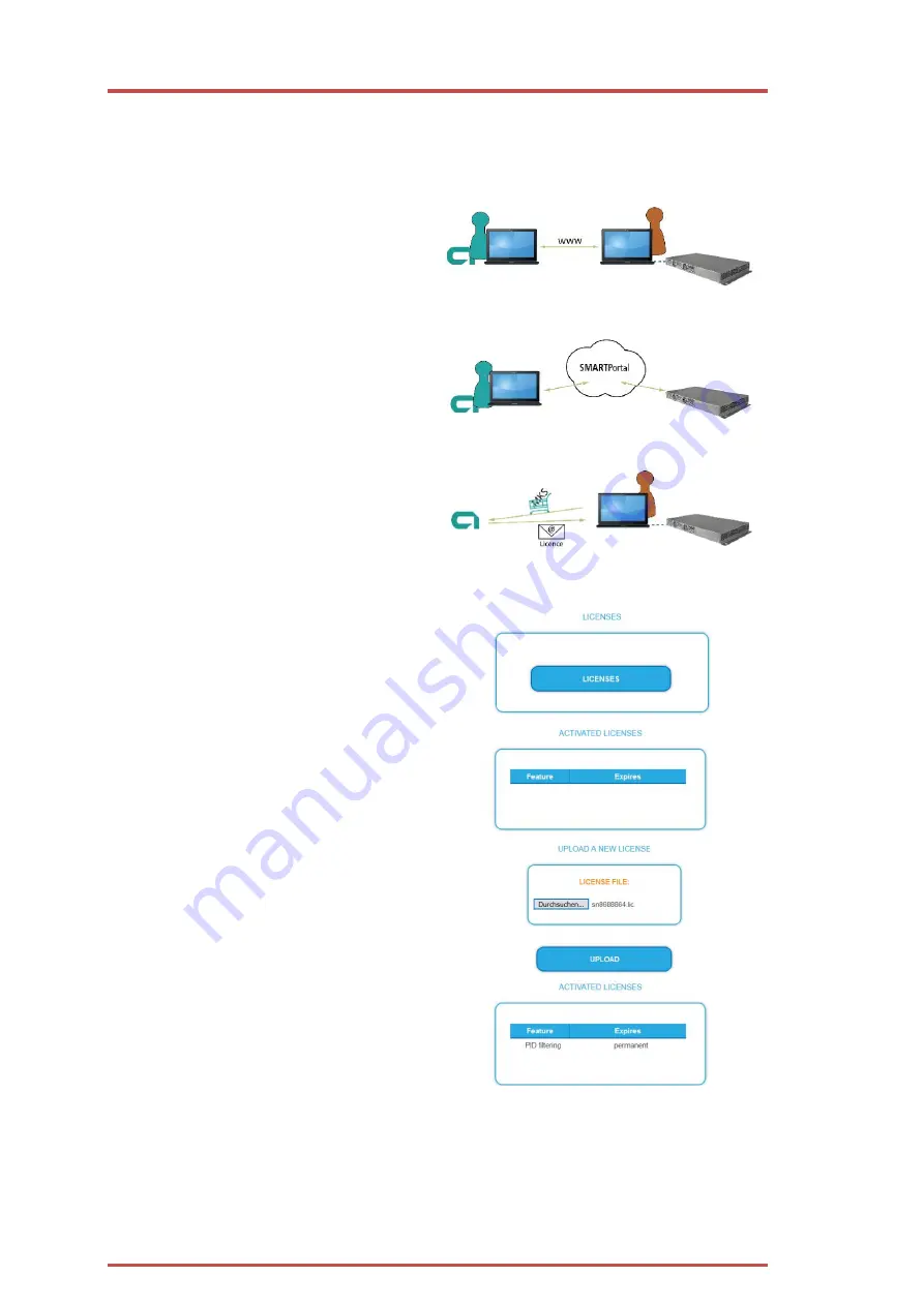
Licenses can be loaded onto the headend in different ways:

By AXING support via remote maintenance software (e.g. TeamViewer):

The headend must be connected to a
PC/notebook via Ethernet.

The notebook requires Internet access.

You need a valid software license and the

current version of the remote maintenance
software.

By the user or AXING support via SMART Portal:

The headend must be integrated into the
SMART Portal and requires Internet access.

If AXING support should upload the license file,
the option Allow AXING support must be

activated for the headend.

By the user in the configuration interface:

You have ordered a software extension and
received a license file by e-mail.

You upload the license file (SN.lic) in the
configuration interface of the headend under

MAINTENANCE>LICENSES.

Note: The new function is only available after a
restart of the headend.

Click on LICENCES.
The dialog ACTIVATED LICENSES will be
opened.

The already activated licenses and their
expiration date are displayed (permanent

means that the license never expires).

Under UPLOAD A NEW LICENSE, select a
LICENSE FILE.

Click on UPLOAD.
The upload will take a few seconds.
The new license is listed in the ACTIVATED
LICENSES dialog.

Reboot the device and log in again.

The new function is only available after a restart of the headend.

Summary of Contents for MIE 4-02

Page 1: ...CHP Compact High Performance Kopfstellen MIE 4 02 MIE 8 02 MIE 4 02 48 MIE 8 02 48 IP zu DVB T2 Betriebsanleitung...

Page 2: ...ramms 28 3 4 7 NIT Version einfrieren bzw benutzerdefinierte Deskriptoren zur NIT hinzuf gen 30 3 4 8 SDT Versionen 31 3 4 9 OTA Upgrade nicht referenzierte PID hinzuf gen 32 3 4 10 Einstellm glichkei...

Page 3: ...3 Technische Verbesserungen nderungen im Design Druckfehler und Irrt mer vorbehalten 3 3 9 8 Verschl sselungs Status Monitoring 57 4 Technische Daten 58 4 1 1 Abweichende Daten MIE 04 02 48 und MIE 08...

Page 4: ...axing com BAs Sicherheitshinweise_9sprachig pdf Benutzen Sie das Ger t ausschlie lich wie in dieser Betriebsanleitung beschrieben und insbesondere nach dem Stand der Technik Wird das Ger t f r andere...

Page 5: ...triebsspannung 36 60 VDC Gemeinsame Features Zwei redundante IPTV Eing nge 900 Mbps pro Modul m glich Wandelt SPTS MPTS in DVB T2 Re Multiplexing PID Filtering PID Remapping Web basierte Konfiguration...

Page 6: ...m Modul A Die LEDs zeigen den Zustand der Ausgangsmodulatoren an Wenn ein Modulator mit Programmen bef llt ist und der Modulator nicht berlastet ist leuchtet die entsprechende LED gr n Wenn ein Modula...

Page 7: ...ein Backup Ger t Beide Ger te verf gen ber zwei redundante IPTV Quellen eine angeschlossen am IPTV Eingang eine angeschlossen an der CAS Schnittstelle Die Verbinding zum CAS Server wird in diesem Fal...

Page 8: ...Konfigurationsschnittstelle Durch das SMARTPortal sind die Konfiguration der Einstellungen oder Software Updates von berall m glich In Problemf llen oder auf Kundenwunsch ist auch eine Unterst tzung u...

Page 9: ...chend geerdet werden 2 1 Montage im 19 Rack Hinweis Bei 19 Zoll Rack Montage muss mindestens einen Freiraum von 5 cm vor und hinter dem Ger t gegeben sein Schieben Sie das Ger t in das 19 Rack Schraub...

Page 10: ...ung bestehen aus 2 M4 Schrauben Verbinden Sie die DC Anschl sse mit 36 60 VDC Wichtig Achten Sie auf die richtige Polung Verwenden Sie ausreichende Leiterquerschnitte 2 4 IPTV Eingang Die MIE ist modu...

Page 11: ...die Schaltzeit betr gt konfigurieren Sie unter Wartung siehe 3 6 3 auf Seite 41 Wenn die Eingangs Transportstreams wieder am IPTV Eingang anstehen dann schaltet die MIE automatisch auf den IPTV Einga...

Page 12: ...rd auf das das Backup Ger t umgeschaltet F r das Backup Ger t muss eine g ltige Lizenz MIS 1 11 installiert sein siehe 3 7 auf Seite 47 Beide Ger te m ssen ber den Control Port miteinander verbunden s...

Page 13: ...ann kann sie Programme verschl sseln Die verschl sselten Programme k nnen von angeschlossenen Teilnehmern mit passenden CA Modulen Smartcard entschl sselt werden Vorrausetzungen Ein entsprechend konfi...

Page 14: ...Betriebsanleitung MIE 4 02 MIE 8 02 14 2020 11 13 Technische Verbesserungen nderungen im Design Druckfehler und Irrt mer vorbehalten ber Control Schnittstelle ber IPTV Schnittstelle...

Page 15: ...MIM 4 02 erweitert werden Trennen Sie das Ger t vom Stromnetz Demontieren Sie die Abdeckplatte auf der R ckseite Setzen Sie das Modul vorsichtig ein Das Modul rastet sp rbar in die Kontakte ein Schrau...

Page 16: ...168 0 145 Subnetz Maske 255 255 255 0 Die MIE 8 02 bzw MIE 8 02 48 enth lt zwei Module A und B Jedes Modul hat eine IP Adresse Werks IP Adresse des Moduls A 192 168 0 145 Werks IP Adresse des Moduls B...

Page 17: ...DE und Englisch EN Die hier getroffene Sprachauswahl gilt f r die Dauer der Sitzung Um sich abzumelden klicken Sie auf auf LOG OUT Hinweise Wird der Browser ohne vorherige Abmeldung geschlossen erfol...

Page 18: ...t CAS Port verwendet 3 2 2 Ausgang Auf der rechten Seite werden die F llst nde der Modulatoren angezeigt 100 Modulator F llstand entsprechen der maximalen Netto Datenrate des Ausgangskanals Wird der m...

Page 19: ...angezeigt Zus tzlich wird die IP Adresse des berwachten Ger ts und dessen Status eingeblendet Wenn ein Ger t als prim res Ger ts eingesetzt wird dann wird im Fehlerfall die IP Adresse des Backup Ger...

Page 20: ...tmen INITIALISIERUNG Die Initialisierung startet mit PHASE 1 3 3 1 Eingangs Streams In Phase 1 werden die IP Adresse der Port die Datenrate in Mbps und der Status der Eingabestreams in einer Tabelle a...

Page 21: ...cken Sie OK der Stream wird hinzugef gt und gescannt Mehrere Streams hinzuf gen Aktivieren Sie zus tzlich die Option Mehrere Streams hinzuf gen Geben Sie die End IP ein Die Streams zwischen der IP Adr...

Page 22: ...dem Modus Passthrough k nnen die Programme eines Eingangs Transportsreams 1 1 zu einem Modulator durchgeleitet werden W hlen Sie den Modus Passtrough aus W hlen Sie den gew nschten Modulator aus Klick...

Page 23: ...weils nur einmal im Netzwerk vergeben werden Unterschiedliche LCN Standards k nnen im Auswahlfeld Region ausgew hlt werden 3 4 1 Auswahl der Programme Damit am HF Ausgang Programme ausgegeben werden m...

Page 24: ...net sind Klicken Sie beim entsprechenden Programm in die Spalte LCN Geben Sie die LCN mit der Tastatur ein oder erh hen veringern Sie die LCN mit den Pfeiltasten Geben f r jeden gew nschten Programmpl...

Page 25: ...ichnet sind Einzelne Pakete k nnen bei Bedarf aus dem Transportstrom gefiltert werden Klicken Sie auf eines der Programme Die Tabelle mit den im Programm enthaltenen Paketen wird ge ffnet Bei den PIDs...

Page 26: ...haben kann dies zu St rungen f hren Desegen werden diese PIDs automatisch re mapped Im Beispiel sind beide Programme dem Modulator M1 zugeordnet 1 Sowohl beim oberen Programm Das Erste als auch beim u...

Page 27: ...ixierten PIDs werden in der Kopfstelle gespeichert Manuelles Remappen Sollen Pakete eine ganz bestimmte OUT PID erhalten dann kann diese manuell eingegeben werden Klicken Sie beim entsprechenden Progr...

Page 28: ...eboten werden arte DE arte FR Klicken Sie auf das zu duplizierende Programm Die Tabelle mit den Programminformationen und inhalten wird ge ffnet Klicken Sie auf Hinzuf gen Das Programm wird 1 1 dupliz...

Page 29: ...n Audio Streams an den Ausgangsmodulator bertragen Wenn Sie ein dupliziertes Programm wieder entfernen m chten dann klicken Sie auf die Schaltfl che Entfernen Hinweise Ein Programm kann nur einmal dup...

Page 30: ...s weil die Receiver die neue NIT automatisch einlesen In manchen L ndern z B Frankreich werden aber die Endanwender dazu aufgefordert einen Sendersuchlauf zu starten Kommt es nun zu dem Fall dass ein...

Page 31: ...n k nnen u U zu St rungen im Netzwerk f hren Klicken Sie nach der Eingabe auf SPEICHERN Die Eingaben werden erst dadurch in der Kopfstelle gespeichert 3 4 8 SDT Versionen Klicken Sie in PHASE 2 auf ER...

Page 32: ...cht definiert In Phase 1 muss bereits ein Transportstrom ausgew hlt sein der die nicht referenzierte PID PIDs enth lt Klicken Sie in PHASE 2 auf ERWEITERTE OPTIONEN Ein Dialog mit zus tzlichen Optione...

Page 33: ...en Ausgang separat eingegeben werden Im folgenden Beispiel wird PID 7496 aus dem Eingangsstrom 239 0 0 0 1 1234 an drei Modulatoren weitergeleitet Klicken Sie anschlie end auf SPEICHERN Die Eingaben w...

Page 34: ...TDT TOT enth lt Diese Tabellen werden an die Ausgangs Modulatoren umgeleitet Fester Eingangs Stream z B 239 0 0 0 1 1234 Ein bestimmter Eingangsstrom wird als Zeitreferenz f r die Ausgangs Modulatore...

Page 35: ...en Modulator aus Nehmen Sie die n tigen ndrungen vor Klicken Sie bei jedem Modulator auf SPEICHERN Erst dadurch werden die nderungen gespeichert ansonsten gehen die nderungen verloren Parameter Allgem...

Page 36: ...nnen mehr Daten in einem Kanal bertragen werden Durch das Verstellen der Bandbreite entsprechen die Kan le nicht mehr dem durch die Norm vorgegebenen Kanalraster Guard Interval Zwischen den gesendete...

Page 37: ...len Netto Datenrate des Ausgangskanals kommt es im Modulator zu einem berlauf Dieser berlauf f hrt zu St rungen Der berlauf des Modulators wird durch die Status LED an der Front des Ger tes rot angeze...

Page 38: ...Betriebsanleitung MIE 4 02 MIE 8 02 38 2020 11 13 Technische Verbesserungen nderungen im Design Druckfehler und Irrt mer vorbehalten...

Page 39: ...ion der Firmware und den Typ der Ausgangsmodulation an Software Version Zeigt die Version der Oberfl che an Seriennummer des Ger ts Prozessortemperatur muss unter 90 C bleiben Bel ftungstemperatur mus...

Page 40: ...auf www axing com im Suchfeld den Artikel eingeben Laden Sie die aktuelle Version auf Ihren PC herunter und entpacken Sie diese Update Unter SOFTWARE DATEI kann eine neue Software f r die Oberfl che i...

Page 41: ...n ein Netzwerk mit DHCP Server einzubinden Statische IP Adresse Verwenden Sie statische IP Adresse um das Ger t mit einer fest vergebenen IP Adresse in ein Netzwerk einzubinden Hier kann die IP Adress...

Page 42: ...r zur ck W hlen Sie Automatisch Manuell zur ckschalten Wenn keine g ltigen Eingangs Streams mehr am IPTV Eingang anstehen dann schaltet die MIE automatisch auf den CAS Port um Das Zur ckschalten muss...

Page 43: ...iges Umschalten auf den redundanten Eingang beim Booten zu vermeiden Bei der Eingabe neuer Streams in Phase 1 werden weitere 60 Sekunden zur Umschaltzeit hinzugef gt um unn tiges Umschalten auf den re...

Page 44: ...zur Startseite 3 6 7 Initialisierungsdaten speichern Unter EINSTELLUNGEN DER INITIALISIERUNG ALS DATEI SPEICHERN k nnen die aktuellen Einstellungen der Initialiserungsphasen 1 bis 3 bernommen und in...

Page 45: ...wurden in ein Ger t mit einer neueren Software Version geladen werden Initialisierungsdaten die mit einer neuern Software Versionen gespeichert wurden k nnen aber nicht in Ger te mit einer lteren Sof...

Page 46: ...6 2 auf Seite 40 W hlen Sie im Feld Status die Option Aktiviert Aktivieren Sie wenn gew nscht die Option AXING Support zulassen Geben Sie im Feld Standort eine Bezeichnung des Standorts des Ger ts ei...

Page 47: ...n Im Feld SNMP Version SNMPv1 oder SNMPv2c w hlen SNMPv2c wird empfohlen Der Community Name das SNMP Passwort lautet per Default public bei Bedarf einen anderen Community Name eingeben Traps Traps k n...

Page 48: ...geschrieben und ist nach einem Neustart leer Der Systemlog wird in den Flashspeicher geschrieben ist also auch nach dem Neustart noch vorhanden W hlen Sie Statuslog Die Eintr ge des Statuslog werden...

Page 49: ...f r die Kopfstelle aktiviert sein Durch den Benutzer in der Konfigurationsoberfl che Sie haben eine Software Erweiterung bestellt und eine Lizenzdatei per E Mail erhalten Sie laden die Lizenzdatei SN...

Page 50: ...ren Ger t an Klicken Sie unter WARTUNG EINSTELLUNGEN DER INITIALISIERUNG ALS DATEI SPEICHERN auf SPEICHERN Speichern Sie die Config dat auf Ihrem Computer Melden Sie sich beim zu Backup Ger t an W hl...

Page 51: ...ase3 Gemeinsamer Ausgangspegel Power fail Fehler der Versorgungsspannung Die interne Spannung ist zu niedrig 11 0 V Temp to high Temperatur zu hoch Die Temperatur des Prozessors ist zu stark angestieg...

Page 52: ...ackup Ger t umgeschaltet Nach dem Umschalten zum Backup Ger t wird auf der Startseite des Backup Ger t der Grund f r das Umschalten angezeigt Replace reason Zus tzlich wird der Status der Verbindung z...

Page 53: ...t manuell ersetzen Es kann manuell auf das Backup Ger t umgeschaltet werden Dies dient zum Beispiel einem Test der Funktion Aktivieren Sie unter WARTUNG DEVICE REDUNDANCY MONITORING STATUS die Option...

Page 54: ...en sind auf Englisch 3 9 1 Globale CAS Einstellungen Enable Simulcrypt Aktivieren oder Deaktivieren von Simulcrypt zur Aktivierung ist eine Lizenz erforderlich Network interface Netzwerkschnittstelle...

Page 55: ...t DVB CSA 2 CSA mit vollst ndigem 64 Bit Schl ssel Scrambling Policy w hlbare Optionen sind All ECMGs Programme die mit diesem SCG verbunden sind werden nur dann verschl sselt wenn alle ECMGs verbunde...

Page 56: ...anten die das Control Word auf sichere Weise enthalten sowie Berechtigungsinformationen Jeder ECM Eintrag entspricht einem generierten ECM Stream Jede SCG erfordert mindestens einen ECM Stream da sons...

Page 57: ...en kann diese Zelle i d R leer gelassen werden Wenn jedoch eine IP Adresse eingegeben wird sind nur Verbindungen ber diese Adresse m glich CAS CA System aus der CAS List Client ID optional Der Wert mi...

Page 58: ...nn alle verschl sselten Dienste Gr n anzeigen dann funktioniert das System ohne Probleme Wenn jedoch irgendein Programm Rot anzeigt werden unter Wartung CAS weitere Informationen angezeigt SCG table s...

Page 59: ...s Messbuchse 1 F Buchse 30 dB 2 F Buchse 30 dB Ausgangsimpedanz 75 Ausgangspegel einstellbar 85 105 dB V Ausgangmodulation Ausgangs Konformit t EN 50083 9 ETSI TS 101 154 ETSI EN300 429 ETSI EN 300 74...

Page 60: ...Redundante Netzteile 2 Hot pluggable Potentialausgleichanschluss 4 mm2 Betriebstemperaturbereich gem EN 60065 10 C 50 C Lagertemperaturbereich gem EN 60065 20 C 80 C Ma e B H T ca 480 43 275 mm 480 43...

Page 61: ...2020 11 13 Technische Verbesserungen nderungen im Design Druckfehler und Irrt mer vorbehalten 61...

Page 62: ...CHP Compact High Performance Headends MIE 4 02 MIE 8 02 MIE 4 02 48 MIE 8 02 48 IP to DVB T2 Operation instructions...

Page 63: ...4 6 Duplicating a program 26 3 4 7 Freeze NIT version or add custom descriptors to NIT 28 3 4 8 SDT table versions 29 3 4 9 OTA upgrade add non referenced PIDs 29 3 4 10 Setting options for TDT and T...

Page 64: ...2020 11 13 Technical improvements changes in design printing and other errors expected 3 4 Technical specifications 57 4 1 1 Deviating data MIE 04 02 48 and MIE 08 02 48 58...

Page 65: ...d axing com BAs Sicherheitshinweise_9sprachig pdf Use the device only as described in these operating instructions and in particular in accordance with the state of the art If the device is used for o...

Page 66: ...r supply 36 60 VDC Common Features Two redundant IPTV inputs 900 Mbps per module possible Converts SPTS MPTS to DVB T2 Remux Crossmultiplex PID Filtering PID remapping Web based configuration Suitable...

Page 67: ...one module A The LEDs 1 4 show the state of the output modulators When a modulator is filled with content and the modulator is not overloaded the corresponding LED lights up green If a modulator is on...

Page 68: ...primary device by a backup device Both devices have two redundant IPTV sources one connected to the IPTV input and one connected to the CAS interface In this case the connection to the CAS server is i...

Page 69: ...vice e g via LAN EoC EoC WLAN Bridge 3G LTE Router With AXING s SMARTPortal a worldwide configuration of all settings or software updates can be ensured On customer request AXING can provide the neces...

Page 70: ...pliance with the safety regulations defined by the EN 60728 11 standard 2 2 Equipotential bonding The device must be connected to the equipotential bonding according to EN 60728 11 Use the equipotenti...

Page 71: ...Each module has its own IPTV interface The MIE 4 02 or MIE 4 02 48 contains one module A Default IPTV address of module A 192 168 0 146 Subnet mask 255 255 255 0 The MIE 8 02 or MIE 8 02 48 contains t...

Page 72: ...ut transport streams are again present at the IPTV input the MIE automatically switches back to the IPTV input This switching back usually takes a little more than a minute 2 6 RF output Each module o...

Page 73: ...backup device its output modulators become active and provide the output signal The output modulators of the primary device are switched off in this case The device redundancy is configured for the b...

Page 74: ...2020 11 13 Technical improvements changes in design printing and other errors expected 13 2 8 1 Options for connecting Via CAS port Via Control port...

Page 75: ...02 The MIE 4 02 can be extended by a further hardware module MIM 4 02 Disconnect the device from the mains Disassemble the cover plate on the back Insert the module carefully The module noticeably sna...

Page 76: ...wn IPTV address Default IP address of module A 192 168 0 145 Default IP address of module B 192 168 0 148 Subnet mask 255 255 255 0 The expansion module MIM 4 02 also has its own IPTV address Default...

Page 77: ...be changed The chosen language applies until the end of the session To log out click LOG OUT Notes If the browser is closed while you are still logged in an automatic logout occurs 2 5 minutes later...

Page 78: ...odulator fill level correspond to the maximal net data rate of the output channel If the current fill level exceeds the maximal fill level it may cause image disturbances e g mosaic images The data ra...

Page 79: ...ee 2 7 on page 12 the front page displays the IP address of the monitored device and its status When a device is used as the primary device the IP address of the backup device that turned off the modu...

Page 80: ...IALIZATION from the main menu The initialization starts with PHASE 1 3 3 1 Input streams In Phase 1 the IP address port data rate in Mbps and status of the input streams are displayed in a table Click...

Page 81: ...address of the stream and its port Click OK the stream will be added and scanned To add multiple streams Activate the option Add multiple streams Enter the End IP Streams are created between the IP A...

Page 82: ...ith the Passthrough mode the programs of an input transport stream can be forwarded 1 1 to a modulator Select the Passtrough mode Select the desired modulator Click OK the stream will be added and sca...

Page 83: ...same Transport stream IDs on the other hand may only be assigned once in the network Different LCN standards can be selected with the drop down menue Region 3 4 1 Assigning programmes So that program...

Page 84: ...ams assigned to a modulator Click on the LCN column for the corresponding program Enter the LCN with the keyboard or increase decrease the LCN with the arrow buttons right of the number Enter a own LC...

Page 85: ...fied by PIDs Packet Identifier Individual packets can be filtered from the transport stream if required Click on one of the programs The table with the packages contained in the program is opened For...

Page 86: ...programs are assigned to modulator M1 1 The IN PIDs 101 to 105 are identical for both the upper program Das Erste and the lower program Eurosport Therefore the PIDs are re mapped in the lower program...

Page 87: ...ck SAVE CHANGES The entered PIDs are saved in the headend 3 4 6 Duplicating a program Programs can be duplicated in phase 2 This allows for example to offer a program in two different languages at the...

Page 88: ...erman audio streams are transmitted to the output modulator in the other the French audio streams If you want to remove a duplicated program click on Remove Notes A program can only be duplicated once...

Page 89: ...end users are asked to start a channel search If it comes to the case that one or more stations are weak to receive then the NIT changes frequently and the end users are always unnecessarily prompted...

Page 90: ...nally the SDT table generation can be deactivated for each modulator It may only be deactivated if a valid SDT is transferred from another PID to the standard PID 17 Otherwise the programmes will not...

Page 91: ...output PID can be the same or different from the input PID Click on the green plus sign next to the line The entered data are inserted If necessary enter additional non referenced PIDs The same input...

Page 92: ...in design printing and other errors expected 31 Then click on the green check mark The changes are accepted To delete click on the trashcan icon to the right of the line The line is deleted Click SAV...

Page 93: ...input stream is used as a time reference for the output modulators Local time zone country code and region ID in TOT can be set with this option NTP Server An NTP server is defined The device connects...

Page 94: ...s reached with a setting of 20 dB the lowest level with a setting of 0 dB Norm In this selection field you can set the norm for the output channel spacing Note Changing the norm works now according to...

Page 95: ...he useful signal The guard interval protects against inter symbol interferences A very long guard interval e g 1 4 leads to a very low data rate A small guard interval is usually sufficient for transm...

Page 96: ...l the modulator overflows This overflow leads to disturbances If the modulator overflows the status LED on the front side of the device lights in red Filtering the programmes reduces the net data rate...

Page 97: ...ou stay on the maintenance page for more than 2 5 minutes an automatic logout will occur and you will have to repeat the login procedure Device Redundancy If a device is used as a backup device for an...

Page 98: ...r SOFTWARE FILE Click under SOFTWARE FILE on Browse Browse for the file on your computer Click on UPDATE The file will be uploaded to the device After this the update of the device begins the remainin...

Page 99: ...ess Use dynamic IP address to connect the device to a network with a DHCP server Static IP adress Use a static IP address to connect the device to a network with a fixed IP address The IP address netm...

Page 100: ...again Choose Automatic Manual Revert If there are no valid input streams left at the IPTV input the MIE automatically switches to the CAS port However switching back must be done manually Options for...

Page 101: ...an additional 30 seconds are added to the switching time to prevent unnecessary switching to the redundant input while booting During entering of new streams in phase 1 an additional 60 seconds are ad...

Page 102: ...e front page will be shown 3 6 7 Save initialization data In the section SAVE SYSTEM INITILIZATION DATA TO FILE you can save the current initilization data from phase 1 to 3 into a file on your comput...

Page 103: ...lization data saved with older software versions can be loaded into the device with a newer Software version Initialization data saved with a newer software versions can not be loaded into devices wit...

Page 104: ...if required the option AXING support allowed In the field Location enter a name for the location of the device This name will appear later in the SMARTPortal to help you identify the device In the fi...

Page 105: ...nother port In the SNMP Version field select version SNMPv1 or SNMPv2c SNMPv2c is recommended The Community Name the SNMP password is public by default if necessary enter a different community name Tr...

Page 106: ...is still available after rebooting the headend The status log is written to RAM and is empty after rebooting the headend Choose Statuslog The entries of the status log are displayed Choose Systemlog T...

Page 107: ...ad the license file the option Allow AXING support must be activated for the headend By the user in the configuration interface You have ordered a software extension and received a license file by e m...

Page 108: ...configuration is to save the configuration data of the primary device and load it into the backup device Log in to the primary device Under MAINTENANCE SAVE INITIALIZATION DATA TO FILE click SAVE Save...

Page 109: ...vel initialization Phase3 Common output level Power fail The internal voltage is too low 11 0 V Temp to high The temperature of the processor rises too high 90 C At this temperature the unit will stil...

Page 110: ...he reason for replacement is displayed on the front page of the backup device Additionally the status of the connection to the primary device is displayed Ending the replacement Switching to the backu...

Page 111: ...ce It can be manually switched to the backup device This can be used to test the function for example Under MAINTENANCE DEVICE REDUNDANCY MONITORING STATUS enable the Force replacement option Then cli...

Page 112: ...for the CAS settings are displayed 3 9 1 Global Settings Enable Simulcrypt Enable or disable Simulcrypt license needed to activate Network interface used for all simulcrypt related network traffic op...

Page 113: ...used DVB CSA 2 CSA with full length keys 64 bit keys Scrambling Policy option values All ECMGs Programs connected to this SCG are scrambled only if all ECMGs are connected Any ECMG Programs connected...

Page 114: ...l word encryption key in a secure manner and private entitlement information Each ECM entry corresponds to one generated ECM stream Each SCG requires at least one ECM stream otherwise nobody is able t...

Page 115: ...t EMM generators are separated by Client ID and this cell can be left empty But if IP address is entered only connections from this address are allowed CAS CA System from the CAS List Client ID option...

Page 116: ...have green light system is working without problems But if any service has red light Maintenance CAS page gives more details SCG table status Once SCG status is green services connected to this SCG ar...

Page 117: ...Operation instructions MIE 4 02 MIE 8 02 56 2020 11 13 Technical improvements changes in design printing and other errors expected...

Page 118: ...30 dB 2 F female 30 dB Outputimpedance 75 Output level adjustable 85 105 dB V Output modulation Output compilance EN 50083 9 ETSI TS 101 154 ETSI EN300 429 ETSI EN 300 744 DVB T2 acc to EN 302 755 mod...

Page 119: ...ggable Equipotential bonding connection 4 mm2 Operating temperature range acc to EN 60065 10 C 50 C Storage temperature range acc to EN 60065 20 C 80 C Dimensions W H D appr 480 43 275 mm Comments ava...

Page 120: ...2020 11 13 Technical improvements changes in design printing and other errors expected 59...

Page 121: ...Operation instructions MIE 4 02 MIE 8 02 60 2020 11 13 Technical improvements changes in design printing and other errors expected...

Reviews: