3: T
he x
Sw
itc
h i
n d
ep
th •
6
Single xSwitch
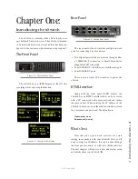
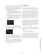
Secure the short rack ear to one side of the xSwitch.
Secure the long ear to the opposing side of the xSwitch.
Double Mount
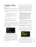
Remove the top lid from both devices. Place side by
side. Place spacer between the two as shown.
Use the four (4) screws provided to secure the two
devices together.
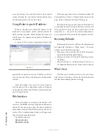
Return the lids and secure. Attach a short rack ear to
either side of the devices.
Web Interface
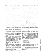
The first time an HTML request is issued to a
xSwitch, a login and password is requested. The default
authentication is:
Username: user
Password: (none)
Home
The home page shows system information and acts
as the default page for xSwitch.
Software Version
: The code version which is used
by the xSwitch.
Temperature
: The temperature reading of the inter-
nal sensor. Alarm status will appear if the temperature is
above acceptable limits.
System Uptime
: The amount of time since the last
boot up.
The Home page also has a button, “Simple Setup”,
which links to the Simple Setup page.
Switch Port Status:
Each port is identified and
information on the link status and PoE usage is reported.
At the bottom of the list of ports is a multicast router
identifier which reports which ports are connected to
devices that manage IGMP reports.
Simple Setup
Simple Setup provides only a Node ID option to the
user. All other configuration options have already been
done for the customer by the Axia Engineers.
Switch Statistics
The Switch Statistics link provides comprehensive
per-port statistics common to Ethernet switchgear. In-
Figure 3-8
Figure 3-9a
Figure 3-9b
Figure 3-10
©2013 Axia Audio


