background image

AXELL D-CSR 3302 US VHF REPEATER


PRODUCT DESCRIPTION AND US

ER’S MANUAL 


Doc PN 0034B-UM Rev. 2.1 

© Axell Wireless Ltd 

1.3.2 Internal Interfaces 

The following internal interfaces are relevant to the user operations: 

  Ethernet port used for setup (and optionally, for remote management) 

  RS232 port used for local setup connection 

  SIM card slot (On Control module, for models supporting a modem) 

  Power and battery switches 

  Backup Battery 


NOTE: The rechargeable battery pack is located internally and is accessed by opening the repeater. 


1-4.  D-CSR with door open 

Summary of Contents for D-CSR 3302

Page 1: ...AXELL D CSR 3302 US VHF REPEATER PRODUCT DESCRIPTION AND USER S MANUAL ...

Page 2: ...rs and the aforementioned advisory services This document has been prepared to be used by professional and properly trained personnel and the customer assumes full responsibility when using them The manufacturer welcomes customer comments as part of the process of continual development and improvement of the documentation in the best way possible from the user s viewpoint Please submit your commen...

Page 3: ... prior notice The information furnished by Axell Wireless in this document is believed to be accurate and reliable However Axell Wireless assumes no responsibility for its use In no event shall Axell Wireless be liable for any damage resulting from loss of data loss of use or loss of profits and Axell Wireless further disclaims any and all liability for indirect incidental special consequential or...

Page 4: ...harmful interference and 2 This device must accept any interference received including interference that may cause undesired operation If not installed and used in accordance with the instructions this equipment generates uses and can radiate radio frequency energy However there is no guarantee that interference will not occur in a particular installation If this equipment does cause harmful inter...

Page 5: ...e No of Antennas Cable Losses Max Allowed Antenna Gain 1 2 39 1 27 2 14 1dBi Compliance with FCC deployment rule regarding the radiation of noise Good engineering practice must be used in regard to the signal booster s noise radiation Thus the gain of the signal booster should be set so that the ERP of the output noise from the signal booster should not exceed the level of 43 dBm in 10 kHz measure...

Page 6: ...ne antenne d un type et d un gain maximal ou inférieur approuvé pour l émetteur par Industrie Canada Dans le but de réduire les risques de brouillage radioélectrique à l intention des autres utilisateurs il faut choisir le type d antenne et son gain de sorte que la puissance isotrope rayonnée équivalente p i r e ne dépasse pas l intensité nécessaire à l établissement d une communication satisfaisa...

Page 7: ...connection or because a spare output has been left un terminated Either of these conditions would impair the system s efficiency No investigation should be carried out until all RF power sources have been removed This would always be a wise precaution despite the severe mismatch between the impedance of an N type connector at 50Ω and that of free space at 377Ω which would severely compromise the e...

Page 8: ...re to comply with these precautions This entire manual should be read and understood before operating or maintaining the repeater Warning Restricted Access Location Access to the Axell unit installation location is restricted to SERVICE PERSONNEL and to USERS who have been instructed on the restrictions and the required precautions to be taken Attention Electrostatic Sensitivity Observe electrosta...

Page 9: ... Location 9 3 3 1 Relative Location of Base Station 9 3 3 2 Cooling and Airflow 9 3 3 3 Wall Compatibility 10 3 3 4 Access to the Repeater 10 4 Physical Installation 11 4 1 Overview of the Installation Procedure 11 4 2 Required Tools and Materials 12 4 3 Unpacking 12 4 4 Bracket Assembly 13 4 5 Wallmount Procedure 13 4 5 1 Requirements 13 4 5 2 Planning the Repeater Location and Drilling 14 4 5 3 ...

Page 10: ... 1 User Accounts 38 7 1 1 Default User Accounts 38 7 1 2 User Access Levels 38 7 1 3 Password Change 39 7 2 Reboot 39 7 3 Axell Shell 40 8 Monitoring and Troubleshooting 41 8 1 Monitoring 41 8 1 1 Logs Screen 41 8 1 2 Alarm Classification and Thresholds 42 8 1 3 Home Screen Monitoring 44 8 1 4 Site Information and System Performance 45 8 2 Module LEDs 46 8 2 1 Control Module LEDs 46 8 2 2 Power Su...

Page 11: ...tures and Capabilities Frequency range 150 174MHz Composite downlink output power D CSR 3302 33dBm for USA and FCC spurious limits Channel selective mode Up to 8 channels with dedicated output power and filter settings Channel width o D CSR 3302 15kHz or 30kHz wider options for low delay IP65 wallmounted unit Remote commissioning and monitoring Via AEM SNMP v1 v2c support Intuitive Web GUI for loc...

Page 12: ... connections ETH SIM for systems with GPRS modem power switches and backup battery 1 3 1 External Interfaces The repeater is secured with two locks located on the repeater door The repeater interfaces are located on both the left and right side panels as follows Left panel Base Donor antenna port Right panel Mobile Service antenna port as well as power GND and alarm connections NOTE Depending on y...

Page 13: ...male connector Power One of the following model dependent 110VAC 230 VAC or 48V DC Power cable supplied GND Grounding lug See section 4 6 Alarms Two external alarms are supported See section 4 10 Alarm cable supplied Modem Antenna Only on units that include a modem The Modem antenna port is located either on the left or right side panel Connection N type female connector Ethernet port Available ex...

Page 14: ...ces are relevant to the user operations Ethernet port used for setup and optionally for remote management RS232 port used for local setup connection SIM card slot On Control module for models supporting a modem Power and battery switches Backup Battery NOTE The rechargeable battery pack is located internally and is accessed by opening the repeater 1 4 D CSR with door open ...

Page 15: ...nnection to the Repeater at any time either before or after mounting and grounding the Repeater 2 1 Base Donor Antenna The Base Donor antenna is usually installed outdoors and is either a directional antenna such as a Yagi or a Panel antenna 2 1 1 Required Antenna Information You will require the following antenna information Antenna type and characteristics Height Length and type of coaxial cable...

Page 16: ...e used to avoid interference c Output power should be reduced to solve any IMD interference issues The Service antenna type depends on the design of the indoors DAS 2 2 1 Required Antenna Information The following antenna requirements specifications and site considerations should be met Type of installation indoor DAS Radiating Cable Service area type and size Antenna type and characteristics Heig...

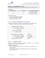
Page 17: ...rehensive range of splitters and Couplers to aid the installation of the internal DAS system Typical specifications as below Splitter Part Number 90 851402 Frequency Band 120 240MHz Split 2 way Max Insertion Loss 0 3dB Split Loss 3 dB Coupler Part Numbers 90 852506 90 852510 Frequency Band 120 240MHz 120 240MHz Coupling 6dB 1 0dB 10dB 1 0dB Max Mainline Loss 1 7dB 0 8dB 2 2 2 3 Installation Criter...

Page 18: ...e manufacturer is helpful All connectors must be clean and dry Waterproof all outdoor connections using silicone vulcanizable tape or other suitable substance as moisture and dust can impair RF characteristics Make sure enough room has been allocated for the bending radius of the cable RF cables must not be kinked cut or damaged in any way Connect the RF cable to the antenna tightly but without da...

Page 19: ...ocated where the BTS signal strength is great enough to be recognized by the system For example a D CSR 3302 85dBm max gain and signal strength of 70dBm at the pickup antenna a gain in the pickup antenna of 10dBi a repeater gain of 85dBm and a server antenna gain of 2dBi the resulting ERP would be 27dBm Losses in cables and other elements would change these figures slightly Repeater location near ...

Page 20: ... the wall on which the Repeater is to be mounted The Repeater wall mount brackets assembly should be fixed to a solid wall these include brickwork blockwork and concrete Due to the weight of the Repeater it is NOT recommended to fix to a hollow wall 3 3 4 Access to the Repeater Plan connection cable clearances the Optical RF and power connections located on the underside of the Repeater will need ...

Page 21: ...3 3 Assemble the brackets and mount the D CSR Repeater on the concrete or brick wall see 4 4 4 For models supporting a modem Insert the SIM card requires opening repeater door Connect the modem antenna external port 5 Ground the Repeater see 4 6 6 If you have not already done so position and install the Base and Mobile antennas in the relevant locations see chapter 2 7 Before powering up the Repea...

Page 22: ...ing the unit 2 Perform a visual inspection to reveal any physical damage to the equipment 3 Verify that all of the equipment listed below is included Otherwise contact Axell Wireless Ltd The D CSR Repeater is shipped with the following equipment D CSR single band Repeater External Alarms Cable P N 90 400006 CD with RMC and documentations Mounting Brackets x 4 Additional supplied installation compo...

Page 23: ...r wall mount brackets assembly should be fixed to a solid wall these include brickwork blockwork and concrete Due to the weight of the Repeater it is NOT recommended to fix to a hollow wall Figure 4 2 M6 Rawlbolt recommended for wallmount IMPORTANT Always check that there are no pipes or cables hidden in the wall beneath the area to be drilled Various pipe and cable detectors are available for thi...

Page 24: ...st the mark and begin drilling slowly so that the bit does not wander from the position The wall should be drilled to a depth which is sufficient to accommodate the full length of the fixing 4 Insert the fixings so that the top of the sleeve anchor section is level with the wall surface 5 Gently tighten the bolt by hand so that the anchor section of the fixing expands and grips the inside of the h...

Page 25: ...this operation 2 Carefully insert the fixing bolts through the mounting lugs of the Repeater and into the sleeve anchor sections of the fixing in the wall and tighten the bolts Figure 4 6 Mount Repeater 4 6 Grounding GND the repeater grounding bolt Ensure that good grounding protection measures are taken to create a reliable repeater site Make sure to use adequately dimensioned grounding cables Th...

Page 26: ...ctronics systems Ensure that lightning protection measures are taken to create a reliable repeater site Protect all coaxial cables and power cables from the transients caused by lightning Fit all cables with suitable lightning protection devices For detailed information please refer to IEC 61024 1 and 61312 1 for international standards for protection of information systems against LEMP Lightning ...

Page 27: ...device is part of the site installation and is not supplied by Axell Wireless Coaxial lightning protection is normally one of these three types Gas capsule High pass and Bandpass There also need to be a protective device installed on the power supply cord Figure 4 9 Protective device installed in connection with the power supply 4 8 Insert SIM Card For models supporting GPRS GSM or PSTN GSM modems...

Page 28: ... strength with the calculated signal strength from the design phase In case of discrepancy check for one of the following Antenna out of direction Antenna tuned to side lobe instead of main lobe Antenna connector or antenna cable faulty Line of sight problem obstruction etc Register the signal strength of the downlink channel for the system operation phase 4 9 2 RF Antenna Connections Refer to the...

Page 29: ...to section 0 6 5 1 NOTE The Alarms connections can be protected with a cover which is screwed in place Figure 4 13 Alarm and Relay Connections PINS DESCRIPTION Pins 3 and 4 External alarm A Pins 5 and 6 External alarm B External Alarms details Pins 3 and 4 5 and 6 Two external alarm sources can be connected to the repeater Alarm operating voltage between 12 and 24VDC Alarm operation criteria can b...

Page 30: ...r on the wall near the unit at an easily accessible distance and location from the unit Circuit breaker minimum requirements D CSR 3302 20AT 115VAC Needs to be SAFETY approved 4 11 2 Switching Power ON Note the following The power switch has two positions on and stand by In the stand by position the repeater is still connected to the power supply but not operational The backup battery is operation...

Page 31: ... and Battery switches located inside the repeater 3 Connect the supplied power cable between the Repeater Power connector and the circuit breaker 4 Turn the repeater on from the circuit breaker 5 Verify the LEDs from the following internal modules are indicating correct operation section 8 1 Control module Power supply modules NOTE To switch power OFF set battery switch to OFF and power switch to ...

Page 32: ...eb Session to the Repeater 5 1 1 Connect the Repeater to the Computer Connect computer to the Repeater Ethernet connection Using the supplied Ethernet cable connect either to the repeater EXTERNAL ETH port if an external ETH port is available on one of the side panels or to the INTERNAL Ethernet port located internally at the side of the Controller The following figure shows an internal ETH connec...

Page 33: ...s 1 Click the Start menu and choose Control Panel 2 In the Control Panel click Network and Internet 3 Click Network and Sharing Centre and then click Local Area Connection The Local Area Connections Status dialog appears with the General tab displayed by default 4 Click the Properties button The Networking tab appears 5 In the Items list double click the Internet Protocol Version 4 TCP IPv4 item 6...

Page 34: ...l Wireless Ltd In the IP address area Enter the IP address 192 168 1 x where x can be any number between 2 and 250 inclusive For example 192 168 1 9 Define the subnet mask as shown 255 255 255 0 8 Click OK The computer communication parameters are now defined and a session to the Repeater can be opened ...

Page 35: ... 1 Open a standard Flash enabled browser e g Internet Explorer or Firefox 2 In the address line enter the IP address of the Repeater http 192 168 1 253 A session will be established with the Repeater and the login dialog appears 3 Enter the default login values as follows Login Name axell case sensitive Password AxellPasswd case sensitive Notes o Do not use the number pad when entering numbers o F...

Page 36: ...ss to a range of configuration options by hovering over the bar See section 5 3 1 for details View Buttons Basic displayed by default and Advanced display options General information show user defined repeater name general identification information and status of external alarms Radio FCC shows current UL and DL power level Channels provides UL and DL channel configuration options and RF output po...

Page 37: ...larm Threshold Section 8 1 1 Alarm Thresholds Define thresholds for all system alarms alarms are displayed in Logs Section 8 1 2 Date and Time Configure the time stamp for dating D CSR events Section 6 4 System Information Display D CSR hardware and software identification information and system performance parameters CPU load average memory usage and network response time ms Section 8 1 4 Passwor...

Page 38: ...dures according to your system installation and requirements Configuring external alarms IP address for connection to the Ethernet network SNMP support TCP IP Modem setup 6 2 Assigning Repeater a Recognizable Name The D CSR is automatically assigned an ID by the AEM In addition it is recommended to assign each repeater a recognizable name that will identify the location site name etc To assign the...

Page 39: ...screen displayed by default A partial image showing only the channel definitions area is illustrated below 2 Define the Downlink and the Uplink parameters for each required channel Set the Centre frequency Set the type of Filter to Low Delay or High Selectivity according to site requirements Set the Power Level according to the following options Max maximum power available according to the number ...

Page 40: ... the figure below are for example only o Lower the Attenuation level step by step until the desired output power level is reached zero attenuation maximum gain NOTE Since the base station is more sensitive than a mobile unit there may be less signal gain from the mobile unit in to the base station UL than in the opposite direction The uplink attenuation can be adjusted more accurately later on onc...

Page 41: ...ss for repeaters that will be connected to the Ethernet network after the initial setup procedure SNMP support requires configuring the agent and trap destination address TCP IP support Modem setup for units supporting a GPRS GSM modem NOTE For units managed via the AEM no configuration procedures are required on the repeater side the repeater access information is configured into the AEM 6 5 1 Co...

Page 42: ...ia DHCP To configure the IP address 1 Hover on the Title area and click on Ethernet 2 For manual IP address configuration Verify that the option Automatically obtain IP address is disabled Set the IP Subnet Mask Default Gateway and DNS addresses Click Apply 3 For DHCP IP address configuration Select Automatically Obtain IP Address DHCP No other settings are required Click Apply The Manual configur...

Page 43: ... be defined via the Axell Shell 5 Enter the destination address device Trap Port and its Community parameters 6 Click Apply SNMP Agent Activating and Configuring The SNMP agent provides inventory management for hosted repeaters on which the SNMP agent is enabled and a table of active alarms in the controller or Fiber system for remote querying The SNMP Agent is responsible for responding to querie...

Page 44: ... the SNMP Agent toggle to ON 3 Set the port and the Read Only community 4 Click Apply 6 5 4 TCP IP and Ethernet TCP IP communication is run over a company s network Therefore each company needs to define the details regarding the configuration IP addresses etc TCP IP Communication Setup 1 Hover on the Home page Title bar and choose Communication from the displayed icons 2 From Device Method select...

Page 45: ...e displayed icons The following dialog appears 2 Verify that Remote Communication is ON 3 Select the Device Method communication method Only the options relevant to your installed modem will be displayed STD DTC Standard AT Data Call ETH TCP Ethernet TCP connection 4 Configure your communication method according to the relevant following section Packet Switched Modem Configuration GSM GPRS NOTE In...

Page 46: ...be performed on the first logout 2 Dial the modem number if PSTN or the data number if SIM card 3 Verify modem LEDs are lit correctly see section 8 1 4 Use any ACT command using a Terminal to test connectivity and responsiveness SIM card Using Single Numbering Scheme If using SNS Single Numbering Scheme calls to the modem within the network are automatically classified as DATA However if calling f...

Page 47: ...d optionally with a secondary telephone number where the repeater can dial in case connection to primary number fails When heartbeat reports and alarms are sent from the repeater to the AEM also the latest information about the status and RF configuration is included This means that the AEM operator always has information about the current status in the AEM database and do not need to call the rep...

Page 48: ...MIN from the user prompt useradmin UseradminPwd23 This account contains user administration privileges Escalation to this level is achieved by issuing command USERADMIN from the user prompt NOTE It is strongly recommended to change the default user names and passwords immediately at commissioning This is done by using the command ACT PASSWORD Please refer to the User Administration section in Comm...

Page 49: ...nd only contain printable characters You can only change the password for the User Name with which the session was accessed To change the Password 1 Hover on the Home screen Title bar and select Password 2 For the current User Name e g axell Enter the New password Repeat the entry 3 Click Apply 7 2 Reboot Caution Use this function in Emergency Cases ONLY To reboot the Repeater 1 Hover on the Home ...

Page 50: ...un some of the commands that are currently not provided by the Web GUI e g user privileges and administration and or for advanced troubleshooting and configurations procedures All configuration and management procedures can be implemented using this interface Please refer to the Help section by clicking the Help on the top right for detailed syntax and available commands To access the Axell Shell ...

Page 51: ...tem SW and HW versions and system performance indicators 8 1 1 Logs Screen The Alarms Log displays the last 100 alarms and or user actions on the remote system in a chronological order The alarms are generated according to user defined thresholds see the following section To display the Logs screen Hover on the Title bar and click Logs The Logs screen appears showing the latest generated alarms an...

Page 52: ...l button to acknowledge all alarm logs 8 1 2 Alarm Classification and Thresholds The user can set the criteria according to which the alarms are generated The criteria include Class and Severity selection whether it will be transmitted to the AEM and more The alarm generation criteria are grouped according to the type of alarms External Alarms User Events Firmware Events etc To access the Alarm Th...

Page 53: ...larm or event Severity The severity level allocated to this event AEM Transmission Whether this alarm is to be sent to the AEM server Affect Relay Whether this alarm will activate the relay Acknowledge Required Whether acknowledgement of the alarm is required Trigger Range Defines the minimum and maximum range outside of which an alarm will be triggered Interval The number of seconds for consecuti...

Page 54: ...ernal modules This information can be used to aid in remotely troubleshooting the repeater This section describes monitoring the Basic view Home screens To view more details click Advanced Figure 8 2 Main Screen Basic View Figure 8 3 Module Status Details Temperature level Input attenuation and Power level Module status External Alarms status Comm Temp Pwr input Batt Status Pwr modules status Refe...

Page 55: ... Performance To view D CSR Site Information Hover over the Title bar click on Site Information Two areas are displayed Performance repeater status dashboard displaying status of key parameters Control Module provides hardware and software version information Site Information provides D CSR identification information Figure 8 4 D CSR Site Information ...

Page 56: ...f Green LED Modem Power On Modem Power is on Off Modem Power is off Green LED Modem Status On Depending on type of call Voice call Connected to remote party Data call Connected to remote party or exchange of parameters while setting up or disconnecting a call Flashing irregular Indicates GPSR data transfer When a GPRS transfer is in progress the LED goes on within 1 second after data packets were ...

Page 57: ...ing or operating with malfunction LED 4 28V Red Slow flash every 10 seconds 28V power supply operating Quick flash 28V power supply not operating or operating with malfunction Examples LED 1 is flashing slowly LED 2 4 are flashing slowly once every 10 seconds power supply unit is operating without problem LED 1 is flashing slowly one or two of the red LEDs are flashing quickly Input power is opera...

Page 58: ... the switch centre over the air interface to the data call number in the SIM card of the GSM module The Control Module is responsible for establishing connections with the Axell Element Manager and to answer incoming calls to the repeater As described in previous sections the Control Module only accepts one login at a time either via Local Maintenance port LMT or modem connection Hence when verify...

Page 59: ...the repeater command prompt NOTE When accessing the modem port the modem might be configured with echo off meaning that the characters entered will not be echoed back to the screen In order to enable echo press Enter Type ATE1 enter invisible The modem replies with OK indicating that the echo is enabled All characters entered will now be echoed back to the terminal program 8 3 2 Trace Modem For tr...

Page 60: ...ber or if the modem contains an illegal modem initialization string the message OK or NO CARRIER will be displayed almost immediately Try to change the modem initialization string The modem initialization string mainly used to configure the remote communication is AT CBST Successful modem initialization strings used by Axell Wireless includes most common first AT CBST 71 0 1 Q3 AT CBST 7 0 1 Q3 AT...

Page 61: ...directly from the modem Go in to Direct Modem Access as described earlier Use the command AT CSQ documented below to read out the signal strength In order to have good signal quality Axell Wireless recommends that the signal strength should be better than 95 dBm If signal strength is lower try to adjust the antennas to get a better signal strength from the donor Documentation of CSQ command from a...

Page 62: ...alization strings AT CBST 71 0 1 Q3 AT CBST 7 0 1 Q3 AT CBST 0 0 1 Q3 AT CBST 0 0 1 Q3 AT CBST 7 0 3 Q3 Please refer to the modem manual for detailed description of the modem initialization strings Problem 3 It is possible to call the repeater from another GSM mobile but not from an analogue modem Solution This problem is most likely related to the modem configuration and or the configuration of t...

Page 63: ...tion in the system the status of the antenna systems as well as the continuity of the cabling should be checked before replacing any modules within the repeater 9 2 Preventative Maintenance The repeater does not require preventative maintenance apart from changing the battery once every three years 9 3 Component Replacement Except for the backup battery none of the modules in the repeater can be r...

Page 64: ...vice should be contacted for advice on a possible module replacement or other action to be taken CAUTION If a shipment of a repeater back to Axell Wireless is made within the period of guarantee the original packing must be used 9 7 Component Replacement None of the modules in the repeater can be replaced without removing the repeater from its mounting and opening the cover of the repeater 9 8 Pro...

Page 65: ...irements 230VAC 50Hz or 110VAC 60Hz or 48 VDC EXTERNAL CONNECTION Local Maintenance Ethernet RF Ports N type female REMOTE CONTROL AND ALARMS External alarm inputs Via modem GSM PSTN via Ethernet and SNMP 2 external alarm inputs NC or NO configurable MECHANICAL SPECIFICATION Dimensions H x W x D 620 x 420 x 300mm 24 4 x 16 5 x 11 8 in Options for larger filters complex frequency bands Enclosure Al...

Reviews: