Awite AwiFLEX XL Original Instruction Manual Download Page 31

Preparing the Gas Analysis System for Use

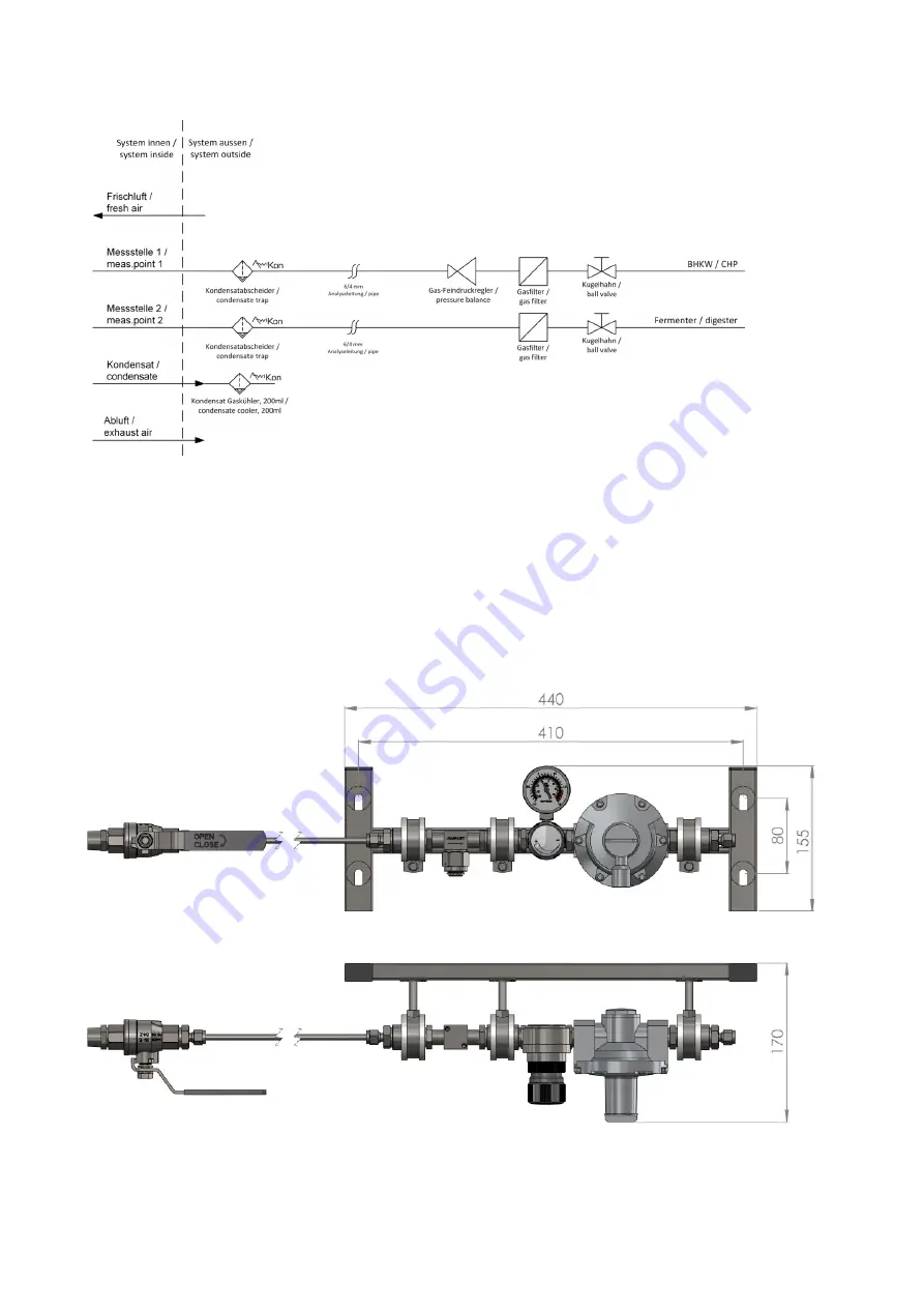
Figure 6: Schematic layout of the extraction points for analysis gas – Exemplary
representation

5.2.6.1.2

Gas extraction fitting up to 16bar (PN16)

For gas extraction from pipes with system pressures between 400mbar and 16bar relative overpressure,
the gas extraction fitting 16bar (PN16) is used. The fitting is designed for indoor installation.

Figure 7: Gas extraction fitting 16bar (PN16) with particle filter (optional)

31

Summary of Contents for AwiFLEX XL

Page 1: ...PART A PRODUCT DESCRIPTION INSTALLATION AND OPERATION AWIFLEX XL AWITE BIOENERGIE Original Instruction Manual Version 18 0...

Page 2: ...ns comments or suggestions please send an email to info awite com Awite Bioenergie GmbH Gr nseiboldsdorfer Weg 5 85416 Langenbach Niederhummel Germany Phone 49 8761 72 162 0 Fax 49 8761 72 162 11 Emai...

Page 3: ...4 Ambient humidity 18 4 4 5 Mains voltage uctuations 18 4 4 6 Overvoltage category 19 4 4 7 Wetness and degree of pollution in the environment 19 4 4 8 Measuring gas pressure 19 4 4 9 Measuring gas f...

Page 4: ...4 Exhaust air Discharge of the Measuring Gas 34 5 2 7 Installation of Humidity and Flow Sensor AwiFLOW 35 5 2 8 Initial Operation 37 6 Handling of the Gas Analysis System 38 6 1 Maintenance 38 6 1 1...

Page 5: ...trical Connection 65 11 AwiWarn 66 11 1 Installation AwiWarn 66 11 2 Required Space 67 11 3 Electrical Connection 68 11 4 Settings and calibration 69 12 Annex 70 12 1 Declarations of Conformity 70 12...

Page 6: ...with it The new owner of the system has to be trained in the regulations referred to If you receive an amendment to the Instruction Manual at a later stage this amendment is also part of the Instructi...

Page 7: ...the cover sheet The type plate on the right hand side panel of the device indicates the device type the required voltage supply and the rated output The manufacturer s address is Awite Bioenergie GmbH...

Page 8: ...is system even in the event of a fault Parts inside the device are under electrical voltage Danger to life by electric shock ALL installation repair maintenance operations on the gas analysis system o...

Page 9: ...ng discharge into the exhaust gas line In case of analysis gas recovery ensure the exhaust gas line is not longer than 20 m and have it lead the exhaust gas only into gas bearing areas in which a maxi...

Page 10: ...rocatalytic gas warning sensor except for biogas with low leakage ow pressure at sampling point max 20 mbar or low ammable gas concentration less than 4 v v Gas warning sensors can deliver too low rea...

Page 11: ...ion General Hazard Point Refer to the documentation Disregarding this can lead to death or serious personal injuries or property damages Warning of dangerous electrical voltage Please also observe the...

Page 12: ...gen up to 100vol and hydrogen sulphide up to 5vol They are neither part of explosion protection nor a warning device They are used without any additional pressure reducing measures for measuring bioga...

Page 13: ...of a hazardous atmosphere 4 2 2 Device category intended for installation in an Ex zone 2 Marking per ATEX and IEC EN 60079 with II 2 3 G Ex nC ec IIA IIC T1 Gc X Gas pipes with combustible or explos...

Page 14: ...ace A gas warning sensor of the ignition protection type II 2G EEx de IIC T4 for intended use as a safety or control device in order to detect methane Zone 2 in accordance with the requirements of Dir...

Page 15: ...ysis System Mounting dimensions mm Device type Width Height Depth AwiFLEX XL 975 900 268 The analysis gas lines are routed to the system from the left hand side via the condensate traps for the manual...

Page 16: ...3 USB connection 4 RJ45 5 Pro bus IN 6 Pro bus OUT 7 Potential equalization 8 Measuring gas cooler AwiCool 9 Measuring gas cooler AwiCool optional 10 Exhaust air 11 External supply of analysis gas 12...

Page 17: ...PLC module 12 Measuring gas cooler AwiCool 13 Absolute Pressure Sensor 14 Oxygen sensor 15 Carbon monoxide sensor 16 diverse electrochemical sensor 17 Mounting brackets sensors 18 Multi gas sensor In...

Page 18: ...C in order to guarantee an exact measurement of the sensors not to damage the electronic components and to be able to operate the unit safely The analysis systems are calibrated at 25 C All detailed...

Page 19: ...tion Pressure outside this range is not allowed because the sensors may be damaged and measured values may be changed With higher or lower pressure corresponding measures must be taken pressure regula...

Page 20: ...re is an Ex zone around the gas analysis system or its pipes or not depends on the probability of the occurrence of an explosive gas mixture The following describes the actions to be taken to avoid an...

Page 21: ...erminals As an additional safety measure the high quality methane sensor that is integrated in the gas analysis system is used to track down possible leaks In case of a leakage the rst valve will cut...

Page 22: ...escription In normal operation and when used as intended these gases are not released The risk of exposure hazards arising from release due to leaks is considered su ciently low according to risk asse...

Page 23: ...5 2 Installation The installation must be performed only by quali ed personnel They must be well familiar with the contents of this manual and any other provided manuals and repair instructions as wel...

Page 24: ...ions DANGER Dangerous electrical voltage is present at the terminals in the terminal box and the cables fed An incorrect connection may lead to electrical hazards and even death For information on the...

Page 25: ...2 Conductor connection X12 3 Conductor connection X13 4 Conductor connection X14 5 Conductor connection X15 6 Conductor connection X16 5 2 2 2 Connection Cable 100 240 V for Power Supply 3 pin 3 x 1...

Page 26: ...tential equalization The gas analysis system must be grounded A screw is provided on the right hand outer side of the stainless steel housing for connecting the grounding cable The grounding cable mus...

Page 27: ...sure that you are using the correct settings for the terminating resistor Mating connectors are supplied with the system Operation of the gas analysis system as part of a Pro bus system terminating re...

Page 28: ...respective sensor Signals outside the range of values have the following meaning 0 mA no signal 2 mA Measured value incorrect 21 mA Sensor overload For information on the wiring of the analogue output...

Page 29: ...ad spaces are avoided If possible the tting sleeve Rp 1 2 should be mounted on the upper side of the gas carrying pipe or on the side so that no condensate can permanently ow into the analysis gas lin...

Page 30: ...to allow closing o the line Filtering Each gas extraction point is tted with a particle lter behind the ball valve This lter also allows a condensation of the gas before the analysis gas pipe in cold...

Page 31: ...presentation 5 2 6 1 2 Gas extraction tting up to 16bar PN16 For gas extraction from pipes with system pressures between 400mbar and 16bar relative overpressure the gas extraction tting 16bar PN16 is...

Page 32: ...tting 16bar PN16 The rst component after the optional particle lter is an adjustable pressure reducer The outlet pressure must always be set to 200 mbar here Installation position gas sampling tting 1...

Page 33: ...Run the pipes in a way that makes it possible to replace them after several years 5 2 6 3 Gas Inlets AwiFLEX XL Due to the high variability of AwiFLEX XL there is no xed allocation of the gas connecti...

Page 34: ...e must not be combined in order to prevent the measuring gas from being pushed back into the device When the discharge reaches the open a hose with an internal diameter of at least 8mm has to be used...

Page 35: ...t gas line is not longer than 20 m and a maximum underpressure or overpressure of 20 mbar prevails in the gas bearing area When introducing exhaust gas into gas bearing lines the possibility of the fo...

Page 36: ...in such a way that the measuring tips are centered in the pipe the ow direction arrow points in the ow direction of the gas and the attenings on the sensor shaft are parallel to the pipeline After con...

Page 37: ...50mm 150mm with ow conditioner 20 x pipe 15 x pipe 9 x pipe 10 x pipe 5 x pipe 2 x pipe Fig 11 E Recommendation for a Setup with a Reduction in the Inlet or Outlet Section 150mm 150mm with ow conditio...

Page 38: ...roughly In order to maintain the warranty a rst maintenance and calibration service is required within the rst 10 months thereafter every 12 months at the latest as a rule Depending on measuring requi...

Page 39: ...Hydrogen sulphide lter A hydrogen sulphide lter is implemented in devices that are tted with a hydrogen sensor For these gas analysis systems the colour of the lling needs to be checked The unused ll...

Page 40: ...o electric shock Prior to replacing fuses you must turn o the main switch and thereby disconnect the gas analysis system from the main power supply The fuses are located in the fuse terminals F1 100 2...

Page 41: ...devices that need to disposed o and use them for further industrial processing 6 5 Product Liability Awite does not assume liability for damages caused by faulty measuring values Please take notice of...

Page 42: ...as this might result in an excessive wear of the sensors The life span warranty applies to a minimal measuring interval of 30 minutes for a measurement at one measuring point which means a maximum of...

Page 43: ...5 100 0 1 0 2 1 2 0 03 0 05 Methane Vol CH4 2 5 100 0 1 4 0 4 16 0 03 1 2 97 100 0 15 0 15 2 4 2 5 0 11 0 11 45 100 0 11 0 24 0 9 3 0 04 0 2 Carbon dioxide Vol CO2 3 100 0 1 3 0 14 5 0 004 0 3 1 25 0...

Page 44: ...y u3 after 1 year 10 C Standard uncer tainty u4 right after calibration 0 C 33 100 1 3 4 1 6 5 0 8 2 4 Carbon monox ide elec tro chem Vol ppm CO 1500 2000 50 70 160 210 20 27 Carbon monoxide infrared...

Page 45: ...s and the non return valves The non return valves are spring closed The electric connection for the compressor incl motor protection switch is located in a terminal box The valves are controlled direc...

Page 46: ...ical desulphurisation Figure 13 Schematic setup of AwiDESULF 100 UL CSA Exemplary representation 1 Compressor 2 Bracket compressor 3 Magnetic valve closed in a de energized state 4 Outlet to fermenter...

Page 47: ...ological desulphurisation Figure 14 Schematic setup of AwiDESULF 200 Exemplary representation 1 Compressor 2 Bracket compressor 3 Magnetic valve closed in a de energized state 4 Outlet to fermenter 5...

Page 48: ...ical desulphurisation Figure 15 Schematic setup of AwiDESULF 200 UL CSA Exemplary representation 1 Compressor 2 Bracket compressor 3 Magnetic valve closed in a de energized state 4 Outlet to fermenter...

Page 49: ...wiDESULF 300 500 Exemplary representation 1 Compressor 2 Bracket compressor 3 Air intake lter 4 Magnetic valve open in a de energized state 5 Exhaust air 6 Outlet to fermenter 7 Magnetic valve closed...

Page 50: ...AwiDESULF 1000 Exemplary representation 1 Compressor 2 Bracket compressor 3 Air intake lter 4 Magnetic valve open in a de energized state 5 Exhaust air 6 Outlet to fermenter 7 Magnetic valve closed i...

Page 51: ...ical desulphurisation Figure 18 Schematic setup of AwiDESULF PureOxygen Exemplary representation 1 Terminal box 2 Connection pure oxygen 3 Magnetic valve closed in a de energized state 4 Outlet to fer...

Page 52: ...a hazardous atmosphere per the ATEX Directive the following assumptions for the medium air form the basis of the interpretation Installation location no zone Interior space of fermenter Zone 2 Check v...

Page 53: ...cal desulphurisation Figure 20 Required space for AwiDESULF 200 UL CSA Exemplary representation Figure 21 Required space for AwiDESULF 300 500 Exemplary representation Figure 22 Required space for Awi...

Page 54: ...ctions please inform Awite in advance about the pipe lengths and the expected biogas volume ows so the right compressor can be chosen A connection with G1 external thread is to be set up on site at th...

Page 55: ...wered by the gas analysis system Specification Connection Cable Valves AWG16 metric equivalent 1 5mm 75 C copper wire only 75 C copper The power supply for AwiDESULF 100 also takes place via the gas a...

Page 56: ...s You can clean the lter by tapping it with the hand Testing and Change interval AwiDESULF 1000 The intake lter has to be cleaned after 250 operating hours at the latest and the lter cartridge must be...

Page 57: ...on the air side of the non return valve Checking the oxygen concentration in the fermenter if the set point of the controller is permanently exceeded due to a valve malfunction or not reached at all d...

Page 58: ...ary system setup including the gas analysis device AwiFLEX The gas samples reach the AwiLAB extension via the maximum of 7 process connections The gas quantities can be recorded with a maximum of 3 mi...

Page 59: ...ther into a gas bag or via a technically permanently leak tight pipe from the installation room normally into the open environment for more information on this see Chapter 5 2 6 4 Exhaust air Discharg...

Page 60: ...ligas counter or the drum gas meter respectively during operation may lead to faulty controls This can cause excessive pressure in the connected collecting gas bags which could then lead to damage and...

Page 61: ...It is thus possible to easily analyse the gas composition in the speci ed negative pressure or from more distant measuring points A special lter prevents water from entering and thus protects the oth...

Page 62: ...sing that is connected directly to the gas analysis system For information on the required space for the AwiVac extension please refer to the following illustrations Figure 27 Required space for AwiVa...

Page 63: ...in the AwiVac 1 Connection analysis gas inlet 6 Mounting plate 2 Connection analysis gas outlet 7 Cable clamps 3 Connection exhaust air 8 Non return valve RM20 4 Water trap 9 Micro membrane pump 5 Pre...

Page 64: ...ase the exhaust gas inside the building WARNING The exhaust pipe of the AwiVac is required for a safe pressure limitation The gas must be able to drain o When discharging into closed gas rooms and lin...

Page 65: ...AwiVac 10 4 Electrical Connection The power supply and control of the AwiVac takes place directly via the gas analysis system The assignment can be found in the included electrical plan 65...

Page 66: ...ted If a hazardous atmosphere is detected the power supply and all signal lines to the gas analysis system must be switched o for safety reasons in order to disconnect potential ignition sources Certa...

Page 67: ...n into the housing from above until the sensor is rmly seated and the display faces forward NOTE The packaging box of the AwiWarn also contains a magnetic pen which is needed to operate the transmitte...

Page 68: ...t not be switched o In case of a gas warning the power supply and all signal lines to the gas analysis system must be switched o on site Once the value is back below pre alarm power to the gas analysi...

Page 69: ...larm gas warning system 20 LEL contact closed if OK Combined fault gas warning system contact closed if OK For information on changing these settings please also contact the manufacturer Honeywell www...

Page 70: ...Conformity The gas analysis system can optionally be designed to be installed in the potentially explosive zone 2 Which declaration applies to the respective device can be determined using the markin...

Page 71: ...utzziele ein It also corresponds to the listed EU guidelines or complies with their protection targets 2014 34 EU 2014 30 EU 2014 35 EU 2011 65 EU Normen auszugsweise Standards in part EN 61010 1 EN 6...

Page 72: ...ntsprechende Detonation srohrsicherung zu verwenden Das Ger t selbst darf in Zone 2 Gas IIC installiert werden Elektrische Steckverbindungen d r fen nur im spannungsfreien Zustand gezogen werden Der I...

Page 73: ...n targets Equipment and Protective Systems Intended for use in Potentially Explosive Atmospheres Regulations 2016 Electromagnetic Compatibility Regulations 2016 Electrical Equipment Safety Regulations...

Page 74: ...al and Electronic Equipment Regulations 2012 Standards in part BS 61010 1 BS 61326 1 BS ISO 12100 1 BS ISO 80079 36 BS 60204 BS 60079 15 Marking II 2 3 G Ex nC ec IIA IIC T1 Gc X Gas pipes with combus...

Page 75: ...radiation liberated gases explosion and implosion The confor mity regarding liberated gases is checked by review of the documentation of the manufacturer The standard does not cover non safety relate...

Page 76: ...ed by DEKRA Germany Risk Assessment A risk assessment according tot he Machinery directive according to ISO 12100 1 Safety of Machinery is re assessed for all product modifications EMC IEC 61326 1 Ele...

Page 77: ...Annex 12 2 Certi cat T V S D UL CSA 61010 1 2012 77...

Reviews: