Awesomatix A700 Evo II Instruction Manual Download Page 43

43

Standard Spare Parts

Parts#

Description

AM01

G

ear Box

AM02

Rear Bar

AM03

Motor Mount L

AM04

Motor Mount T

AM05

Rear Holder

AM06

Steering Block

AM07R

Servo Holder Right

AM07L

Servo Holder Left

AM08

Shocks Holder

AM0

9

Steering Rod

AM10

Steering Plate

AM11

Tower

AM12

Battery Holder

AM13

Spur Holder

AM14

Steering Arm

AM15

Battery Nut

AM16

Servo Saver Arm

AM19

Upper Arm Holder

AT03

Spool Axle

AT04

Main Shaft

AT06

Antenna Holder

AT12

Spur Nut

AT13

W

heel Hex

AT14

Turnbuckle

AT15

Bearing Spacer

AT20

Spur Axle

AT21

Pivot Ball

AT22

Rear Body Holder

AT23

GD Case1

AT24

GD Case2

DT02

Bearing Housing

ST01

Front Axle

ST02

Rear Axle

ST03

Ball Stud

ST05

Shock Rod

ST06

G

ear Axle

ST07

Outdrive

ST08

Steering Nut

ST0

9

Upper Collar

ST10

2mm Pin

ST13

Front Universal Bone

ST14

Rear Universal Bone

ST16

U-

J

oint Cross

ST17

Universal Ring

ST20

GD Shaft

ST21

Servo Rod

P01

Ball 

J

oint1

P02

Ball 

J

oint2

P03

Arm Ball Cap

P04

Arm Hasp

P05

Sway Bar 

J

oint

P06

Downstop Collar

P07

Arm Clip

P08

C-Drive

P0

9

Shock Screw Holder

P10

Diff Cover 

P11

Gear Tube

P12

Sway Bar Holder

P13

Ball Ends Set

P14

Bumper Set

P15

Foam Bumper

P16

Lock Ring

P17

Plastic Cross

SS01

Servo Saver Set

DG1

Damper Gauge

C01

STD Lower Deck

C02

Top Deck L

C03

Top Deck T

C04

Suspension Arm

C05

Rear Steering Arm

C07

Carbon Bumper

S

W

B10

Sway Bar 1.0mm

S

W

B11

Sway Bar 1.1mm

S

W

B12

Sway Bar 1.2mm

S

W

B13

Sway Bar 1.3mm

Parts#

Description

DL1

STD Damper Left

DR1

STD Damper Right

SPR01

STD Shock Spring

SPR02

Shock Rod 

G

uide

SPR03

Shock Pointer

SPR05

Body Clip

SPR06

W

ire Ring

SPR07

E

-Ring

G

01

22T Bevel 

G

ear

G

02

27T Bevel 

G

ear

G

03

25T Bevel 

G

ear

G

05

20T Plastic 

G

ear

G

06

10T Plastic 

G

ear

B106RS

MR106RS Bearing

B85

MR85 Bearing

B84RS

MR84RS Bearing

BF85RS

MF85RS Bearing

B74RS

MR74RS Bearing

PI

N

01

1.5x7.8 Pin

PI

N

02

1.5x5.8 Pin

OR05

G

D O-Ring

OR03

11mm 

O-Ring

SH0.1

6x8x0.1mm Shim

SH0.5

6x3x0.5mm Spacer 

(

Silver

)

SH1.0

6x3x1.0mm Spacer 

(G

ray

)

SH1.75

6x3x1.75mm Spacer 

(

Black

)

SS3

X

3

M3x3 Set Screw

SS3

X

4

M3x4 Set Screw

SS3

X

5

M3x5 Set Screw

SS3

X

12

M3x12 Set Screw

SS3

X

14

M3x14 Set Screw

SRS

Spring Rating Screw

RHS

Ride Height Screw

SB25

X

8

M2.5x8 Button Head Screw

SB3

X

5

M3x5 Button Head Screw

SB3

X

6

M3x6 Button Head Screw

SB3

X

10

M3x10 Button Head Screw

SF3

X

5

M3x5 Flat Head Screw

SF3

X

6

M3x6 Flat Head Screw

SF3

X

8

M3x8 Flat Head Screw

SF3

X

10

M3x10 Flat Head Screw

Optional parts

LA1

Long 

U

pper Arm Set

AM18

F

ront Holder

AT25

Turnbuckle Long

SS3

X

8

M3x8 Set Screw

GD1

G

ear Diff Set

BD1

Ball Diff Set

AT01

DiffCase1

AT02

Diff Case2

ST04

Diff Nut

ST15

Diff Ring

ST18

Diff Axle1

ST19

Diff Axle2

DT01

Diff Cage

DT06

Diff Stop

TB38M

F3-8M Thrust Bearing

B2.4

2.4mm Ball

SPR04

Diff Spring

OR02

BD O-Ring

OR04

14mm 

O-Ring

OW1

One-Way Axle Set

AT05

OW Housing

ST22

OW Outdrive

BF1015RS

F6700RS Bearing

ST11

Bushing R

ST12

Bushing S

P18/19

Ball Joint S Set

DC-S

Diff Covers S Set

Summary of Contents for A700 Evo II

Page 1: ...A A7001 10 SCALE TOURING CAR INSTRUCTION MANUAL...

Page 2: ...ments Follow the operating instructions for the radio equipment at all times Never touch rotating parts of the car as this may cause injury Keep the wheels of the model off the ground when checking th...

Page 3: ...ut is 2 55 Right side servo location is recommended for low profile servos only and provides beneficial weight distribution Left side servo location is possible for both standard and low profile servo...

Page 4: ...C05 Rear Steering Arm x2 AT21 Pivot Ball x4 SB3X5 SB3X8 SH1 0 SH0 5 AT21 AM06 AM14 ST03 SH1 75 SB3X8 ST03 STEP 1 AM06 SB3X5 ST03 SH1 0 SH1 0 SH1 0 AT21 SB3X8 C05 ST03 Notes 1 Apply a thin CA glue on...

Page 5: ...m the screwdriver end It will help at the Front Universals assembling STEP 2 FINISHED PIN01 PIN01 ST10 SPR07 ST01 ST16 ST16 ST17 ST13 STEP 2 1 Insert a 2 5mm flat screwdriver tip into ST17 Universal R...

Page 6: ...TEP 3 FINISHED Make 2 Rear Universals Tip Use a 2 5mm flat screwdriver to unclamp ST13 Rear Axle ST10 SPR07 PIN01 ST02 ST16 ST14 Assembling disassembling method 1 Unclamp ST02 Rear Axle a bit 2 Take o...

Page 7: ...It will demand the appreciable efforts for the first time For disassembly hit to the end face of the Axle or press down on it B106RS AT15 B106RS P16 AT13 Make 2 Front Make 2 Rear B106RS B106RS P16 AT1...

Page 8: ...he free action of the ball joint with a minimal backlash STEP 5 STEP 5 FINISHED P04 SB2 5X8 SB25X8 M2 5x8 Button Head Screw x8 C04 Suspension Arm x4 P04 Arm Hasp x4 Make Front Right and Front Left Mak...

Page 9: ...swing freely Snap P03 Ball Cups on AT21 Balls REAR AT21 AT21 AT21 AT21 P06 P06 SF3X8 SF3X8 SF3X8 SF3X8 SS3X5 SS3X5 SH0 5 SH0 5 SH0 5 SH0 5 FRONT SF3X8 M3x8 Flat Head Screw x8 SS3X5 M3x5 Set Screw x4 S...

Page 10: ...inly They are obligatory for installation even if Sway Bars aren t used These Sway Bar Holders are necessary for suspension arms upward travel restriction and setting Upstop parameters Attention The d...

Page 11: ...SRS RHS SPR03 P09 DR1 DL1 SPR01 ST05 Note Initial position of RHS Ride Height Screw Don t tighten up SRS Spring Rating Screw at this stage STEP 9 cont d Assemble 2 Right Shocks and 2 Left Shocks SS3X3...

Page 12: ...D STEP 10 cont d Mount Front and Rear Shocks SF3X10 M3x10 Flat Head Screw x6 SH1 75 6x3x1 75mm Spacer Black x4 AM08 Shocks Holder x2 SF3X10 SH1 75 AM08 SF3X10 SF3X10 SH1 75 Note Lay down Dampers into...

Page 13: ...g Plate x1 AM10 SB3X6 B84RS AT21 SH1 0 SS3x12 ST08 SB3X6 B84RS B84RS Shown for left side servo location SB3X6 SH1 0 SB3X6 B84RS ST08 Adjust B84RS bearing position to achieve free AM09 Rod sliding at m...

Page 14: ...B3X6 M3x6 Button Head Screw x2 B106RS SH0 5 SB3X6 AM01 G03 SPR06 B106RS SH0 5 SB3X6 Snap SPR06 Wire Ring on G03 Bevel Gear INNER ACKERMANN change Slide AM10 Steering Plate to desired position Use SB3X...

Page 15: ...06RS G03 STEP 17 P10 P10 SH0 1 P11 AM01 Gear Box x1 G03 25T Bevel Gear x1 P11 Gear Tube x1 B106RS MR106RS Bearing x1 SH0 1 6x8x0 1mm Shim x1 P10 Diff Cover x2 SF3X6 M3x6 Flat Head Screw x10 Note Use S...

Page 16: ...ew x1 SS3X4 M3x4 Set Screw x2 PIN02 1 5x5 8 Pin x2 G02 PIN02 SS3X4 B106RS AT20 SS3X4 PIN02 SF3X5 AM13 ST06 B84RS B84RS SB3X5 AM03 G01 SB3X5 AM02 SB3X5 B106RS 0 7mm 0 7mm STEP 21 Tread Lock Attention D...

Page 17: ...17 SF3X6 x5 SF3X6 STEP 23 STEP 24 SF3X6 M3x6 Flat Head Screw x6 x4 SF3X6 x4 For transverse motor layout For longitudinal motor layout For transverse motor layout...

Page 18: ...10T Plastic Gear x4 ST07 Outdrive x2 DT02 Bearing Housing x2 B106RS MR106RS Bearing x2 B85 MR85 Bearing x2 B74RS MR74RS Bearing x2 SH0 1 6x8x0 1mm Shim x1 OR05 GD O Ring x2 Fill with silicone oil Use...

Page 19: ...4 x16 B85 ST15 ST18 ST07 Apply silicone oil ST07 ST19 TB38M SPR04 x4 ST04 Apply silicone oil This ball differential is sealed and can be filled by silicone oil of the proper viscosity So it is no nee...

Page 20: ...out Press on ST07 Outdrive and rotate it to enter into meshing with the Inner Diff Block Axles Then snap ST07 Outdrives completely Diff tightening change Press on this ST07 Outdrive and rotate it to e...

Page 21: ...optional STEP 35 FINISHED OW1 One Way Axle Set not included AT05 OW Housing x1 ST22 OW Outdrive x2 BF1015RS F6700RS Bearing x2 ST22 BF1015RS AT05 BF1015RS ST22 Press on ST07 Outdrive and rotate it to...

Page 22: ...ft upper arm P01 P02 P13 1 P13 1 P13 2 P13 3 P13 3 P13 2 P13 2 P13 3 P13 2 P13 2 P13 3 P13 3 AT14 AT14 AT14 AT14 AT14 AT14 AT14 AT14 Notes The given rods and arms sizes are approximately for 4 front c...

Page 23: ...ton Head Screw x8 SS3X14 M3x14 Set Screw x2 SH1 75 6x3x1 75mm Spacer Black x12 SH1 0 6x3x1mm Spacer Gray x4 Notes Use other combinations of SH0 5 SH1 0 and SH1 75 Spacers under appropriate Pivot Balls...

Page 24: ...SF3X6 B84RS SB3X6 SF3X6 AT04 AT04 Note Use 12mm wrench for AT12 Nut tightening Spur gears not included up to 104T 64p 77T 48p for transverse motor up to 98T 64p 73T 48p for longitudinal motor Check up...

Page 25: ...al shims between AM04 Motor Mount and AM02 Rear Bar or motor 10 5mm Use SH0 5 SH1 75 shims for motors with jutting front bearing shell SF3X10 SF3X10 AM04 SF3X10 Use SH0 5 SH1 75 shims for pinions 43T...

Page 26: ...bon Bumper AM05 Rear Holder P14 1 Lower Bumper P14 2 Front Body Post P14 3 Rear Body Post P14 4 Body Holder P15 Foam Bumper AT22 Rear Body Holder x2 x1 x1 x1 x2 x2 x4 x1 SF3X10 C07 P14 1 P14 2 P14 4 P...

Page 27: ...ded SS01 1 SS01 2 SS01 3 SS01 4 AM16 SS01 5 AT21 SB3X6 SS01 3 SS01 1 SS01 2 Attach Servo Saver Springs as shown Select Servo Saver Horn SS01 1 or SS01 2 according to the type of servo you use SB3X5 SB...

Page 28: ...tion Low profile servo is shown Tighten up SB3X5 SB3X8 crews to fix the servo fully STEP 52 Low profile servo left side mounting is shown SF3X5 x4 Cut off the tip of this Ball End to size specified sn...

Page 29: ...n a flat board Note Apply thin CA glue on all carbon parts edges to protect and seal them SB3X6 M3x6 Button Head Screw x3 SB3X8 M3x8 Button Head Screw x8 ST09 Upper Collar x2 SH1 0 6x3x1 0mm Spacer Gr...

Page 30: ...ront and rear of the chassis To increase front flex remove these SB3X6 screws To increase rear flex remove some SF3X6 screws and add one M3x8 set screw To increase rear flex remove some SF3X6 screws T...

Page 31: ...at right side servo Battery Holders adjustment 1 Choose the desirable battery position 2 Slide Battery Holders to achieve 0 2 0 6mm clearance between them and the battery 3 Tighten up all SF3X10 scre...

Page 32: ...ervo AM15 AM12 AM15 SF3X6 SF3X6 SF3X6 Transverse battery taping is possible This method reduces the influence of the battery on the car flex SF SS Screw Use SF SS Screw on Motor Mount as adjustable in...

Page 33: ...33 BATTERY MOUNTING TECHNIQUE cont d NiMH battery installation technique...

Page 34: ...included transponder not included battery not included wheels not included Receiver Battery Transponder Speed controller Receiver Battery Transponder Note Change spur gear without dismounting of C03 T...

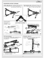
Page 35: ...sion caster change for this adjustment Adding 4 caster shortens wheelbase by 1mm Use Ride Height Gauge for Upstop Downstop measuring Reactive Caster setting is possible Use SS3X4 screws for Upstop and...

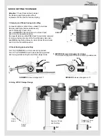
Page 36: ...le position Decrease B distance slide P09 Shock Screw Holder outward to increase Spring rate only at the fixed Damping rate value Use SRS Spring Rating Screw to unlock Shock Screw Holder and to lock i...

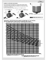
Page 37: ...much There are two Damper Action Modes symmetric and asymmetric modes At symmetric Damper Action Mode the compression and rebound strokes are equivalent At asymmetric Damper Action Mode the compressi...

Page 38: ...3x8 SS3x14 SS3x14 SB3X6 M3x6 Button Head Screw x2 SB3X5 M3x5 Button Head Screw x2 SS3X8 Set Screw x4 SS3X14 Set Screw x8 ST09 Upper Collar x4 AM18 Front Holder x1 AT25 Turnbuckle Long x8 AM18 REAR ST0...

Page 39: ...39 FINAL DRIVE RATIO CHART...

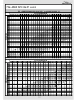
Page 40: ...40 FINAL DRIVE RATIO CHART cont d...

Page 41: ...41...

Page 42: ...42 standard initial setup...

Page 43: ...B11 Sway Bar 1 1mm SWB12 Sway Bar 1 2mm SWB13 Sway Bar 1 3mm Parts Description DL1 STD Damper Left DR1 STD Damper Right SPR01 STD Shock Spring SPR02 Shock Rod Guide SPR03 Shock Pointer SPR05 Body Clip...

Page 44: ...WWW AWESOMATIX COM AWESOMATIX INNOVATIONS LLP PARTNERSHIP No OC353017 RUSSIA UNITED KINGDOM Email support awesomatix com All rights reserved Copyright Awesomatix Innovations LLP 2011...

Reviews: