


3
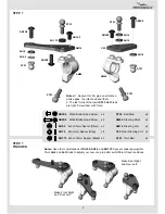
LET’S START
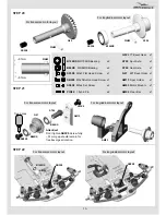
Four main configurations of the A
7
00 car layout are possible.
Some building steps have different variants depending on a desirable configuration.
Longitudinal motor layout is good for 8.5T
-
17.5T motors due to minimal transmission power loss and lower
drive train ratio of
2.08
. Drive train ratio at transverse motor layout is
2.55
.
Right-side servo location is recommended for low-profile servos only and provides beneficial weight distribution.
Left-side servo location is possible for both standard and low-profile servos and provides wider weight balance range.
SERVO
SERVO
SERVO
SERVO
II.
M
otor layout - transverse
Servo location - l
e
ft side
IV.
M
otor layout - longitudinal
Servo location - l
e
ft side
ESC
MOTOR
III.
M
otor layout -
l
ongitudinal
Servo location - right side
ESC
MOTOR
I.
M
otor layout - transverse
Servo location - right side
ESC
MOTOR
ESC
MOTOR
RX
RX
RX
RX


