background image


AVTECH Software Inc.

Installation 


Room Alert 26W

‘Network’ port indicates Link status and should light up and remain a solid green or orange color. 
The right LED below the ‘Network’ port indicates Activity status and should blink with network 
activity on the port. The color of this LED can be green or orange as well. When the device 
reboots, the Link LED will turn on and off several times. If the Link LED remains unlit and the 
Activity LED is blinking orange, please refer to the ‘Performing Firmware Recovery’ section of 
the ‘Advanced Topics’ chapter. This is an RJ-45 port.

External Environment Sensor Channels

 (digital sensor channels) — Sensors such as 

AVTECH’s Digital Temperature Sensor, Digital Temperature/Humidity Sensor, Digital Power 
Sensor and others in the future can be connected to these sensor channels. This is an RJ-11 port.

Wireless Sensor Hub


Signal Strength Indicator

 — These three LEDs indicate the signal 

strength of the last WiSH Sensor to communicate with the Room Alert 26W unit. Signal strength 
will be indicated by the number of illuminated LEDs. A single lit LED indicates a low signal 
strength while three lit LEDs indicates a high signal strength. If low signal strength is indicated 
for a specific WiSH Sensor, then that sensor should be moved or repositioned to a better location.

Digital, Switch & Flood Sensor Alarm Indicators

 — These three LEDs indicate the current 

alarm status of sensors connected to each of the three corresponding sensor ports or channels. If 
the LED is green, then there are currently no sensors in an alarm state for that type of sensor. If 
the LED is red, then one or more sensors of that type are in an alarm state and the web interface 
for Room Alert 26W should be reviewed for more insight.

F

G

H

I

J

K

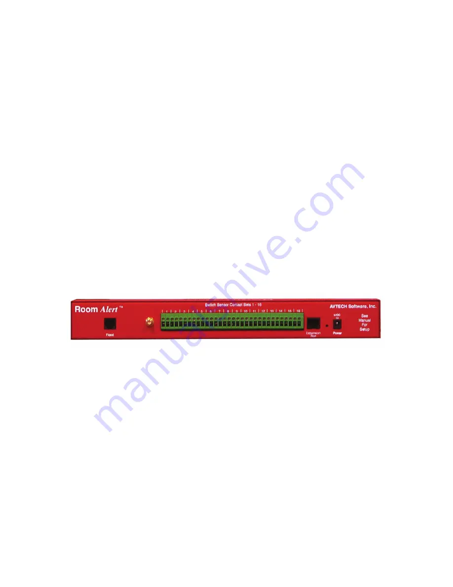
Back View (shown here without rack mounting brackets)

Flood Sensor Cable Port

 — Connect the RJ-11 end of the leader cable of an AVTECH Flood 

Sensor Cable here in order to utilize the built-in (internal) Flood Sensor. This is an RJ-11 port.

Antenna RPSMA Connector

 — Connect the wireless antenna 

(not included with Room Alert 24E)


to the connector. This antenna provides enhanced communication with WiSH Sensors.

Switch Sensor Contact Sets

 — Connect any AVTECH switch-based environment sensor to a set 

of sensor contacts for monitoring by the Room Alert 26W unit. Any switch sensor device with a 
set of voltage-free dry contacts can be attached to a set of sensor contacts. AVTECH has many 

sensors available for monitoring environment and other conditions.

Expansion Port

 — This port exists for future expansion. Do not connect any sensors or cables to 

this port until AVTECH releases or approves devices that are specifically designed to utilize this port.

Reset Button

 — Press this button to reboot the Room Alert 26W unit. If the button is pressed 

and held for 5 seconds, the unit will reset to the factory default settings and reboot.

Main Power Port

 — Connect the ‘AVTECH 5v 1A Power Adapter’ to this port to power the 

C.

D.

E.

F.

G.

H.

I.

J.

K.

Summary of Contents for Room Alert

Page 1: ...Temperature Humidity Power Flood More with Logging Automatic Server Shutdown Alerting Wireless Sensor Monitoring Room Alert 26W Phone Fax Web 401 847 6700 401 847 6701 AVTECH com User s Guide Referen...

Page 2: ...cknowledgements AlertScript AVTECH AVTECH Software the AVTECH Software Logo the AVTECH System Manager Character AVTECH com AVTECHSoftware com Environment Alarm Environment Monitoring Made Easy Environ...

Page 3: ...ct Included Sensors And Accessories 9 Step 5 Check Room Alert 26W Firmware Version 10 Configuration 11 Alert Methods 11 Email 11 Initial Email Setup 12 Testing 12 Email To SMS 13 SNMP 13 SNMP Queries...

Page 4: ...Panic Button 21 Dry Contacts 21 Additional Screens And Interfaces 22 Network 22 Security 22 Advanced 23 Help 23 About 23 Web Interface 24 Advanced Topics 26 Upgrading Firmware 26 Unit Accessible Altho...

Page 5: ...through Room Alert 26W s web interface and your favorite web browser Because each Room Alert 26W ID box is SNMP enabled it can easily be monitored via SNMP savvy applications like PageR Enterprise Ope...

Page 6: ...temperature humidity power flood and room entry monitoring of the computer room data center or other facility Monitoring of digital temperature and humidity is possible at an unlimited number of loca...

Page 7: ...ckage may be individually wrapped and contain additional supporting components Please remember to keep these components together as they will be required for proper setup If you received additional co...

Page 8: ...alarm status of sensors connected to each of the three corresponding sensor ports or channels If the LED is green then there are currently no sensors in an alarm state for that type of sensor If the...

Page 9: ...m being able to detect a main power failure and send an immediate alert when that occurs Then attach the other end of the power adapter to the Power port on the Room Alert 26W unit only if the Room Al...

Page 10: ...r Invalid IPAddress subsection below before continuing Once the desired Room Alert 26W unit is displayed select it from the list to perform an action on it Selecting multiple units will cause the acti...

Page 11: ...is not available on your network and access to a time server on the internet is not possible Microsoft has various help files available that explain how to configure a computer on the local network to...

Page 12: ...octets as the static IP address assigned to the computer i e IP address of computer 192 168 2 3 IP address of Room Alert 26W 192 168 2 4 If the IP address of the Room Alert 26W unit is still not updat...

Page 13: ...A The Digital Temperature Sensor provides a real time digital temperature reading at the location of the temperature probe Position the sensor in the desired location running the sensor cable back to...

Page 14: ...ox Expansion Port This port exists for future expansion Do not connect any sensors or cables to this port until AVTECH releases or approves devices that are specifically designed to utilize this port...

Page 15: ...t PageR can therefore be used to perform SNMP Get requests and receive SNMP Traps Email Email alert notifications are configured in the Room Alert 26W web interface on the Email tab of the Settings sc...

Page 16: ...entered in the Mail Server Address field the Room Alert 26W unit must be assigned static IP settings and have a DNS server IP address set Testing A test email can be sent using the Send Test Email but...

Page 17: ...format for many available service providers This is the largest database of this type on the web However if your service provider is not listed please contact them by phone for the proper format and...

Page 18: ...ed properly in the software application in order to retrieve the SNMP MIB Objects that will return sensor data from the Room Alert 26W unit to the monitoring software SNMP Traps SNMP Traps are sent fr...

Page 19: ...t sensor status will be displayed on the Status screen of the Room Alert 26W web interface The status icon displayed will be a gray circle if a sensor is connected although an alert threshold is not s...

Page 20: ...eckbox If receiving an alert notification on cable disconnect is also desired be sure to check the Alarm On Disconnection checkbox Digital Sensors The alert thresholds for any attached digital sensors...

Page 21: ...al Humidity Sensor and AVTECH Digital Power Sensor Digital Temperature Sensor Digital Temperature Humidity Sensor Digital Power Sensor Switch Sensors Switch sensor alert thresholds are set using the S...

Page 22: ...f sensor does not allow threshold monitoring like digital sensors Users can still turn the logged status information into graphs or charts via other applications The most important benefits here are k...

Page 23: ...s are modified on the Temperature row under Internal Sensors using the High and Low columns The temperature scale used for alert thresholds must match the temperature scale selected on the Advanced ta...

Page 24: ...e AVTECH Digital Power Sensor allows real time voltage amperage wattage and overall power consumption readings for the device plugged into it Alerts can be initiated based upon consumption levels This...

Page 25: ...ow Sensor allows a real time notification of air flow status change i e air flow going on or off This is an instant plug play sensor that connects to one of the switch sensor contact sets via a low vo...

Page 26: ...server IP address and subnet mask in the appropriate fields and click the Save Settings button NOTE If configuring static IP settings on the Room Alert 26W unit be sure that the settings assigned are...

Page 27: ...lp screen provides links to online support and information resources for the Room Alert 26W as well as information regarding telephone and email support Directly below the Room Alert 26W Help heading...

Page 28: ...s the DHCP name screen name date and time display NOTE If the date displayed is 2 14 36 the Room Alert 26W is currently unable to connect to a time server Please verify that the network has a connecti...

Page 29: ...gs screen Below these two rows is the sensor display area The sections displayed from top to bottom are Internal Sensors Digital Sensors Switch Sensors and then Wireless Sensors Next to the sensor blo...

Page 30: ...ot be located although is accessible via a web browser skip to the Unit Accessible Although Not Discoverable section below Navigate to the location where the Room Alert 26W Firmware Update file was sa...

Page 31: ...ing used and close or disable all software firewalls anti virus application and or pop up blockers Open the AVTECH Device Discovery Utility and press the reset button the button next to power port on...

Page 32: ...Protect Your IT Equipment Don t Wait Until It s To Late AVTECH com...

Reviews: