background image

INSTRUCTIONS

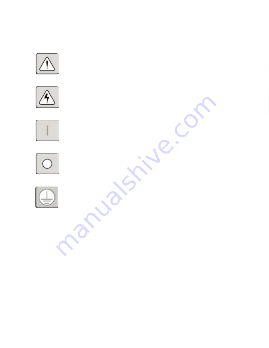
This symbol is intended to alert the user to the presence of important operating and 
maintenance (servicing) instructions in the literature accompanying the appliance. 

DANGEROUS VOLTAGE

This symbol is intended to alert the user to the presence of uninsulated 
dangerous voltage within the product’s enclosure that may be of sufficient 
magnitude to constitute a risk of electric shock to persons. 

POWER OFF

This symbol indicates the principal on/off switch is in the off position. 

POWER ON

This symbol indicates the principal on/off switch is in the on position. 

PROTECTIVE GROUNDING TERMINAL

This symbol indicates a terminal which must be connected to earth ground 
prior to making any other connections to the equipment. 

Summary of Contents for DSR DSR800

Page 1: ...DSR Installer User Guide For models DSR800 DSR1161 DSR2161 DSR4160 ...

Page 2: ...ulated dangerous voltage within the product s enclosure that may be of sufficient magnitude to constitute a risk of electric shock to persons POWER OFF This symbol indicates the principal on off switch is in the off position POWER ON This symbol indicates the principal on off switch is in the on position PROTECTIVE GROUNDING TERMINAL This symbol indicates a terminal which must be connected to eart...

Page 3: ...ing There are trademarks of Avocent Corporation OSCAR is a registered trade mark of Apex Inc All other marks are trademarks or registered trademarks of their respective owners 2003 Avocent Corporation All rights reserved DSR Installer User Guide ...

Page 4: ...dio communications Operation of this equipment in a residential area is likely to cause harmful interference in which case the user will be required to correct the interference at his own expense Canadian Notification This digital apparatus does not exceed the Class A limits for radio noise emissions from digital apparatus set out in the Radio Interference Regulations of the Canadian Department of...

Page 5: ...ocal Port Operation Controlling your System at the Local Port 17 Viewing and Selecting Ports and Servers 17 Configuring OSCAR 20 Resetting your Keyboard and Mouse 26 Displaying Version Information 27 Chapter 4 Terminal Operations Accessing the Terminal Menu 31 Appendices Appendix A FLASH Upgrades 37 Appendix B Technical Specifications 38 Appendix C Technical Support 39 ...

Page 6: ......

Page 7: ...Contents Features and Benefits 3 Safety Precautions 5 1 Product Overview ...

Page 8: ......

Page 9: ...tly relieves KVM cable volume in the rack by utilizing the innovative DSRIQ module and single CAT 5 cabling This allows you higher server density while providing greater airflow and cooling capacity The DSRIQ module is powered directly from the server and provides Keep alive functionality whether or not the DSR unit is powered up Access the DSR via network connection No special software or drivers...

Page 10: ...y is established the DSAuthentication Service software manages the system s user permissioning DSView polls the server for access permissions on power up and every time a switch is initiated for the most current permissions possible A refresh is also available for immediate updates to a user s access profile In addition to the permissioning function the DSAuthentication Service also stores pertine...

Page 11: ...mage to equipment please observe the following precautions Do not use a 2 wire power cord in any Avocent product configuration Test AC outlets at computer and monitor for proper polarity and grounding Use only with grounded outlets at both the computer and monitor When using a backup power supply UPS power the computer the monitor and the DSR unit off the supply NOTE The AC inlet is the main disco...

Page 12: ...not compromised Mechanical Loading Mounting of the equipment in the rack should be such that a hazardous condition is not achieved due to uneven mechanical loading Circuit Overloading Consideration should be given to the connection of the equipment to the supply circuit and the effect that overloading of circuits might have on overcurrent protection and supply wiring Consider equipment nameplate r...

Page 13: ...Contents Getting Started 9 Installing the DSR Unit 11 2 Installation ...

Page 14: ......

Page 15: ...seT Ethernet may be used Avocent recommends a dedicated switched 100BaseT network Getting Started Before installing your DSR refer to the list below to ensure you have all items that shipped with the DSR as well as other items necessary for proper installation Supplied with the DSR DSR Unit Local country power cord Rack mounting brackets Null modem cable DSR Installer User Guide DSR Quick Install ...

Page 16: ...ning DSView The DSR supports both bootP a subset of DHCP and Static IP addressing Avocent recommends that IP addresses be reserved for each unit and that they remain static while the DSR units are connected to the network For additional information on how the DSR uses the TCP protocol see Appendix D Figure 2 1 The DSR in a Network Configuration DSR2161 Digital User Analog User Authentication Servi...

Page 17: ...sk of electric shock or damage to your equipment Do not disable the power cord grounding plug The grounding plug is an important safety feature Plug the power cord into a grounded earthed outlet that is easily accessible at all times Disconnect the power from the unit by unplugging the power cord from either the electrical outlet or the unit 1 3 5 7 9 11 13 15 2 4 6 8 10 12 14 16 LAN 100 240V 1 0A...

Page 18: ...ter it stops blinking press the Enter key to access the main menu NOTE The DSR unit may be rack mounted in a 1U configuration The DSR does not support a 0U configuration To configure the DSR hardware 1 You will see the Terminal Applications menu with six options Select option 1 Network Configuration Figure 2 3 Network Configuration Menu 2 Select option 1 to set your network speed When possible you...

Page 19: ...Settings Control Panel Mouse 2 Click on the Motion tab 3 Set the Acceleration setting to none and the speed setting to the default of 50 To connect a DSRIQ module to each server 1 Locate the DSRIQ for your DSR unit 2 Attach the appropriately color coded ends to the keyboard monitor and mouse ports on the first server you will be connecting to this DSR unit 3 Attach one end of the CAT 5 cabling tha...

Page 20: ...ar of the DSR to your network 2 Then power up all attached systems NOTE Your software registration key will be necessary for all installations Internet Explorer 5 0 or higher must be installed on all systems running DSR software To install your DS software See the DS Installer User Guide that ships with your software ...

Page 21: ...nts Controlling your System at the Local Port 17 Viewing and Selecting Ports and Servers 17 Configuring OSCAR 20 Resetting your Keyboard and Mouse 26 Displaying Version Information 27 3 Local Port Operation ...

Page 22: ......

Page 23: ...rver names Viewing and Selecting Ports and Servers Use the Main dialog box to view configure and control servers in the DSR system To access the Main dialog box Press Print Screen to launch OSCAR The Main dialog box will appear Figure 3 1 Main Dialog Box Viewing the status of your DSR system The status of servers in your system is indicated in the far right column of the Main dialog box The follow...

Page 24: ...ee state with no server selected The status flag on your desktop displays Free Soft switching After you press Print Screen to initially open the OSCAR GUI you can select servers without displaying OSCAR This is called a soft switch To configure servers for selection without displaying OSCAR 1 Press Print Screen to launch OSCAR The Main dialog box appears 2 Click Setup Menu The Menu dialog box appe...

Page 25: ...text box it selects the text for editing and enables the Left and Right Arrow keys to move the cursor Press Enter again to quit the edit mode Print Screen Backspace Toggles back to previous selection if no other keystrokes have been typed Print Screen Alt Ø Immediately disconnects the user from a server no server is selected Status Flag displays Free Print Screen Pause Immediately turns on screen ...

Page 26: ... Figure 3 2 Setup Dialog Box Setup Features to Manage Routine Tasks for your Servers Feature Purpose Menu Change the server listing between numerical by port and alphabetical by name Change the Delay Time before OSCAR displays after pressing Print Screen Flag Change display timing color or location of the status flag Security Set passwords to protect or restrict server access Enable the screen sav...

Page 27: ...me column in the OSCAR GUI If the servers are displayed by port number the Port button is depressed in the Main dialog box and the indicator defaults in the Port column in the OSCAR GUI To set a delay time for OSCAR GUI 1 Type in the number of seconds you want to delay display of the OSCAR GUI after you press Print Screen 2 Click OK Setting a time to delay display of the OSCAR GUI allows you to co...

Page 28: ...on of the flag on the desktop OSCAR Status Flags Flag Description Flag type by name Flag type by port number Flag indicating that the user has been disconnected from all systems To access the Flag dialog box 1 Press Print Screen The Main dialog box will appear 2 Click Setup Flag The Flag dialog box appears Figure 3 4 Flag Dialog Box To determine how the status flag is displayed 1 Select Name or Po...

Page 29: ...ages after your console remains unused for a user definable time delay Once engaged your console will remain locked until you press any key or move the mouse You will then need to type in your password to log in Use the Security dialog box to lock your console with password protection set or change your password and enable the screen saver To access the Security dialog box 1 Press Print Screen The...

Page 30: ... 1 Press any key on the keyboard or move your mouse The Password dialog box appears Type your password and then click OK 2 Press Print Screen to start the OSCAR GUI To remove password protection from your console 1 From the Main dialog box click Setup Security the Password dialog box appears Type your password and then click OK 2 In the Security dialog box single click and press Enter or double cl...

Page 31: ... is selected The status flag displays Free To exit the screen saver mode Press any key or move your mouse The Main dialog box appears To turn off the screen saver 1 In the Security dialog box clear Enable Screen Saver 2 Click OK To immediately turn on the screen saver 1 Press Print Screen then press Pause 2 This command only works when the user is connected to a server Assigning server names Use t...

Page 32: ...r press Escape to exit the dialog box without saving changes To list servers alphabetically by name Press Alt N or click Name in the Main dialog box Resetting your Keyboard and Mouse If a keyboard or mouse locks up you may be able to reestablish operation of these peripherals by issuing a reset command The reset command sends a hot plug sequence to the server which causes the mouse and keyboard se...

Page 33: ... DSR as well as display keyboard and mouse information for the currently selected server This information facilitates system troubleshooting and support For optimum performance keep your firmware current To display version information 1 Click Version in the Commands dialog box The Version dialog box is displayed 2 Click X to close the Version dialog box Figure 3 9 Version Dialog Box ...

Page 34: ...28 DSR Installer User Guide ...

Page 35: ...Contents Accessing the Terminal Menu 31 4 Terminal Operations ...

Page 36: ......

Page 37: ...re Sun Keyboard Layout Code and Exit Each are discussed below Network Configuration menu The DSR is configured for network access through this option When it is selected you will have access to the addressing that allows the DSR to be positioned in your network Security Configuration menu This menu option allows you to configure DSR authentication security When it is selected you will be given two...

Page 38: ...d selection allows you to upgrade your DSR firmware with upgrades available from Avocent You may use the Toggle Boot Firmware command to switch from your current firmware back to the original factory firmware installed on your DSR unit For more information see Appendix A FLASH Upgrades Enable Debug Messages menu This menu option allows you to configure the DSR to display messages regarding the sta...

Page 39: ...and a new one 3 Re enter the new password to verify CAUTION This password places your DSR terminal in a secure mode This password should be guarded like any network password and care should be taken to avoid forgetting or misplacing it There are no means for recovering a lost password Exit menu This menu selection will return you to the ready prompt ...

Page 40: ...34 DSR Installer User Guide ...

Page 41: ...Contents Appendix A FLASH Upgrades 37 Appendix B Technical Specifications 38 Appendix C Technical Support 39 Appendices ...

Page 42: ......

Page 43: ...control 2 If the DSR is not on turn it on now After approximately 10 seconds press any key to access the main menu 3 You will see the Terminal Applications menu with six options Select Option 3 Firmware Management NOTE The current version of your firmware will be displayed on the Firmware Management screen 4 Select Option 1 FLASH Download 5 Type the IP Address of your TFTP server and press Enter 6...

Page 44: ... AWG three wire cable with a three lead IEC 320 receptacle on the power supply end and a country dependant plug on the power resource end AC Frequency 50 60 Hz Auto Sensing Temperature 32 to 104 degrees Fahrenheit 0 to 40 degrees Celsius operating 4 to 158 degrees Fahrenheit 20 to 70 degrees Celsius nonoperating Humidity 10 to 95 noncondensing Agency Approvals USA UL FCC Canada cUL ICES 003 Japan ...

Page 45: ...astest possible service 1 Check the pertinent section of the manual to see if the issue can be resolved by following the procedures outlined 2 Check our web site at www avocent com support to search the knowledge base or use the on line service request 3 Call Avocent Technical Support for assistance at 888 793 8763 Visit the Avocent web site at http www avocent com support and click on Getting Sup...

Page 46: ...40 DSR Installer User Guide ...

Page 47: ... tested under load 2 If defect or malfunction was caused by abuse mishandling unauthorized repair or use other than intended 3 If unauthorized modifications were made to product 4 If unreported damages occurred in any shipment of the product 5 If damages were due to or caused by equipment or software not provided by Avocent 6 If the unit is used with non grounded or incorrectly polarized AC power ...

Page 48: ... 353 61 715 292 Fax 353 61 471 871 Avocent Asia Pacific Singapore Branch Office 100 Tras Street 15 01 Amara Corporate Tower Singapore 079027 Tel 656 227 3773 Fax 656 223 9155 Avocent Germany Gottlieb Daimler Straße 2 4 D 33803 Steinhagen Germany Tel 49 5204 9134 0 Fax 49 5204 9134 99 Avocent Canada 50 Mural Street Unit 5 Richmond Hill Ontario L4B 1E4 Canada Tel 1 877 992 9239 Fax 1 877 524 2985 Em...

Reviews: