background image

AVK SEriES 29 HydrAnt 

inStAllAtion, opErAtion & mAintEnAncE mAnuAl


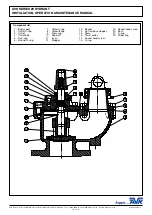
 component list

  1.  Body squat

  2.  Outlet O-ring

 3.  Outlet

  4.  Outlet bolt

  5.  Dust cap

  6.  Bonnet O-ring

  7.  Gland O-ring

  8.  Gland flange

  9.  Stem cap

 10.  Cap  bolt

 11.  Insert

 12.  Stopper

 13.  Bonnet

 14.  Nut for loose stopper

 15.  Stem

 16.  Thrust  collar

 17.  Socket head screw

 18.  O-ring

 19.  Socket head screw

 20.  Bush

 21.  O-ring

 22.  Wiper  ring

AVK Valves Pty Ltd, 559A Grand Junction Road, Wingfield, SA 5013, Australia - T: +61 8 8368 0900 - E: [email protected] - W: www.avkcivil.com.au                                 Version number 3

COPYRIGHT©AVK GROUP A/S 2017 

                                                                                      pp. 3 of 6 

Summary of Contents for 29 Series

Page 1: ...sential that the staff that undertake these operations be adequately trained The hazards of pressurised liquids and gases can be severe and it is the responsibility of the users to ensure that trained competent staff undertake these duties This manual has been designed to assist but it can never fully replace quality training in the workplace AVK technical staff will always be available to answer ...

Page 2: ...E MOST SUITABLE VALVE WILL BE SUPPLIED FOR YOUR SPECIFIC PURPOSE AVK Valves Pty Ltd 559A Grand Junction Road Wingfield SA 5013 Australia T 61 8 8368 0900 E enquiries avkau com au W www avkcivil com au Version number 3 COPYRIGHT AVK GROUP A S 2017 pp 2 of 6 Materials Castings body bonnet stem cap stopper gland flange Ductile Iron to AS 1831 Grade 500 7 Coating Fusion bonded epoxy FBE Stem isolation...

Page 3: ...ange 9 Stem cap 10 Cap bolt 11 Insert 12 Stopper 13 Bonnet 14 Nut for loose stopper 15 Stem 16 Thrust collar 17 Socket head screw 18 O ring 19 Socket head screw 20 Bush 21 O ring 22 Wiper ring AVK Valves Pty Ltd 559A Grand Junction Road Wingfield SA 5013 Australia T 61 8 8368 0900 E enquiries avkau com au W www avkcivil com au Version number 3 COPYRIGHT AVK GROUP A S 2017 pp 3 of 6 ...

Page 4: ...o a maximum temperature of 70 C Minimum liquid temperature must be above freezing Insulation is essential for external temperatures on 0 C and below to a limit of 10 C They are rated for a maximum working pressure of 16 bar unless otherwise agreed and deliver a minimum of 2000 litres per minute at 1 7 Bar gauge They are normally supplied as CLOCKWISE CLOSE CC denoted by a WHITE plastic insert on t...

Page 5: ...ot melt and socket head screws 17 3 The bonnet can now be removed vertically with the stem cap 9 and stopper 12 it can be easily lifted out of the body If the hydrant is fitted with a loose stopper 12 this will remain on the valve seat when the bonnet is lifted out of the body 1 Remove O ring 6 4 Replace O ring 6 locating in body 1 and if necessary lubricate with an approved grease 5 Before locati...

Page 6: ...re The autofrost valve will seal above 0 5 Bar pressure Ensure personnel are not directly above outlet during this part of the procedure Then close hydrant and check that autofrost valve is draining correctly 5 Refit outlet dust cap to outlet TEST On completion of Maintenance requirements 1 Check all item are located correctly 2 Check that all screws are secure 3 Remove dust cap 5 from outlet 3 SA...

Reviews: