background image

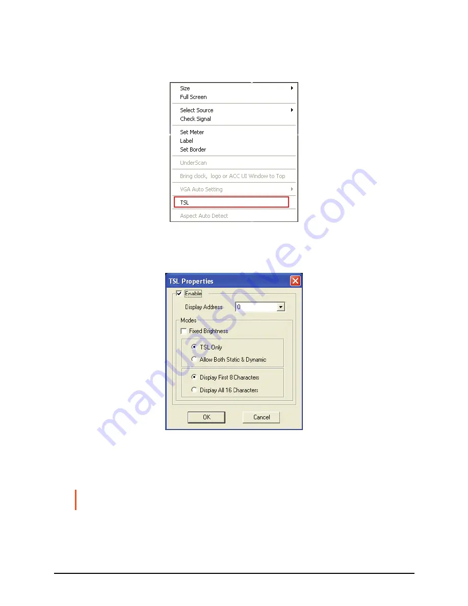
For an Individual Window 

1.


Right-click on a window, then click 

TSL


2.


Ensure that 

Enable

 is selected (with checkmark). If it is unchecked, only 

static labels will be displayed. 


3.


Specify the 

Display Address

 (ranges from 

0

 to 

126

). The address should 

match the TSL controller configured address corresponding to the router 
output feeding the corresponding Avitech input. 

NOTE:

 Use the mouse to right-click each individual window to set the 

TSL Display 

Address


42 

Summary of Contents for Rainier-4a

Page 1: ...User s Manual Rainier 4a 4a1V 4d 4d1V RS 232 Revision 1 1 March 2010 ...

Page 2: ...tten permission of Avitech International Corporation Avitech International Corporation may have patents patent applications trademarks copyrights or other intellectual property rights covering the subject matter in this document Except as expressly written by Avitech International Corporation the furnishing of this document does not give you any license to patents trademarks copyrights or other in...

Page 3: ...e vii Statement of Compliance vii Preface viii Welcome viii About this Manual viii 1 Getting Started 1 1 1 Package Contents 1 1 2 Product Features 2 Specifications 3 Operating Features 4 1 3 Identifying the Front Hardware Component 5 1 4 Identifying the Rear Hardware Components 5 1 5 Getting Your Rainier Ready for Use 6 Basic Hardware Connections 6 Cascading 8 1 6 Using the Galaxy Configuration So...

Page 4: ...ecalling Presets 82 3 Avitech ASCII Protocol 85 3 1 Setting the RS 232 Port 85 3 2 Setting the HyperTerminal s COM Port 86 3 3 Entering the ASCII Z Command Interface 87 3 4 ASCII Z Command Format 89 ZC 89 ZF 90 ZJ for Rainier 4a1V 4d1V only 90 ZM 91 ZP 92 ZT 92 ZX 93 A Firmware Upgrade 94 A 1 Installing the Device Driver 94 A 2 Updating the Firmware 97 Rainier 4x1V Firmware 97 FPGA Firmware for Ra...

Page 5: ...ect to the limitation of liability set forth next Limitation of liability Avitech s liability under this warranty shall not exceed the purchase price paid for the defective product In no event shall Avitech be liable for any incidental special or consequential damages including without limitation loss of profits for any breach of this warranty If Avitech replaces the defective Product with a repla...

Page 6: ...ls under conditions other than those specifically covered by the Hardware Warranty will be repaired at the price of parts and labor in effect at the time of repair Such repairs are warranted for a period of ninety 90 days from date of reshipment to customer Extended Warranty Options Avitech offers OPTIONAL Extended Warranty plans that provide continuous coverage for the Product after the expiratio...

Page 7: ...stalled and used in accordance with the instruction manual may cause harmful interference to radio communications Operation of this equipment in a residential area is likely to cause harmful interference in which case the user will be required to correct the interference at his own expense Properly shielded and grounded cables and connectors must be used in order to meet FCC emission limits Avitec...

Page 8: ...nne 1999 5 EC German Dieses Produkt entspricht den Bestimmungen der Europäischen Richtlinie 1999 5 EC Greek To προϊόν αυτό πληροί τις προβλέψεις της Ευρωπαϊκής Οδηγίας 1999 5 EC Icelandic Þessi vara stenst reglugerð Evrópska Efnahags Bandalagsins númer 1999 5 EC Italian Questo prodotto è conforme alla Direttiva Europea 1999 5 EC Norwegian Dette produktet er i henhold til bestemmelsene i det europe...

Page 9: ...Australia and New Zealand C Tick Marking and Compliance Notice Statement of Compliance This product complies with Australia and New Zealand s standards for radio interference vii ...

Page 10: ...splays embedded audio meter alarms tally and aspect ratio marker Up to four Rainier processors can be cascaded in a single display About this Manual This manual contains comprehensive information about your Avitech Rainier to help you operate the device Throughout the manual the following conventions are used to distinguish elements of text NOTE provides additional hints or information that requir...

Page 11: ...and the look of t accessories may be different from the ones shown in this manual After unpacking the shipping carton you should find these standard items 1 1 Package Contents Avitech Rainier DVI to VGA Adapter RS 485 Cascading Cable DVI Cascading Cable optional when purcha 2 or more Rainier sing optional w e Rainier hen purchasing 2 or mor RJ 50 GPI Terminal Block Standard Powe customers only r C...

Page 12: ...lution Rainier 4a N A not applicable 4 1440 900 Rainier 4a1V 1 4 1920 1200 Rainier 8a1V 1 8 1920 1200 Rainier 12a1V 1 12 1920 1200 Rainier 16a1V 1 16 1920 1200 Rainier 4d N A 4 SD SDI 1440 900 Rainier 4d1V 1 4 SD SDI 1920 1200 Rainier 8d1V 1 8 SD SDI 1920 1200 Rainier 12d1V 1 12 SD SDI 1920 1200 Rainier 16d1V 1 16 SD SDI 1920 1200 z Automatic sensing of SD SDI and composite analog input z Computer...

Page 13: ... Video Inputs Automatic sensing via BNC SD SDI NTSC 525i PAL 625i 525p 59 94 625p 50 Composite analog NTSC PAL Number of inputs 4 DVI I Automatic detection Input resolution up to 1920 1200 WUXGA For background display or for cascading multiple modules together Number of input 1 Audio Display 2 channels of embedded audio per SD SDI audio Output Resolution up to 1920 1200 WUXGA via DVI I connector N...

Page 14: ...ontrol via RS 232 cable or multiple operations up to four Rainier three DVI z Two Rainier can fit in a single rack unit space for a maximum of eight video inputs and one multimedia input z SD SDI units can de embed one stereo audio pair for meter displays and each audio source can be outputted via AES audio z Single scaleable DVI input for use with VGA DVI component inputs z Computer DVI I input c...

Page 15: ...ent Ref Component Description Power LED Lights green when the Rainier is powered on n 1 4 Identifying the Rear Hardware Components IMPORTANT Refer to the next table s Description column for availability of the ports on your particular model 5 ...

Page 16: ...input cascade from other Rainier series device NOTE This port is not available for the Rainier 4a and 4d DVI I Output t DVI I connector for output to monitor display ID u Rotary dial to assign unique addresses in systems with two or more units GPI v RJ 50 connector for GP input output w RS 485 in out RS 485 connectors for serial cascading input output DIP switches For updating the firmware left di...

Page 17: ...orts for audio cascade NOTE Skip this step for the Rainier 4a 4a1V models only 3 Connect the RS 232 cable to the RS 232 port for signal from PC 4 Connect the DVI I cable to the DVI I Input port for video input to the Rainier NOTE Skip this step for the Rainier 4a 4d models 5 Connect the DVI I cable to the DVI I Output port for video output to the monitor display 6 Make sure to assign a unique addr...

Page 18: ...tech Rainier to 1 set the rotary ID on the third Avitech Rainier to 2 and so forth can be other values as long as both are different from each other s setting 2 Connect one end of the DVI cascading cable to the DVI I Output port of Rainier ID 0 Master module and the other end to the DVI I Input port of Rainier ID 1 Connect one end of another DVI cascading cable to the DVI I Output port of Rainier ...

Page 19: ...ne end of the DVI cable to the DVI I Output port of the last Rainier cascaded and the other end to the monitor display you may need to use a DVI to VGA adapter for monitor display with VGA input NOTE The analog part of the DVI I Input port is bypassed relays in case the module has no power or is defective A powered down or a defective unit in the chain will not compromise the whole system other mo...

Page 20: ... available 1 6 Using the Galaxy Configuration Software The Galaxy configuration software is designed for all Avitech Multiviewer modules This program requires no installation and should not be run from a read only device such as an optical disc This section introduces the Galaxy software for setting up your system NOTE Make sure the Rainier is powered on and connected properly to your computer see...

Page 21: ...our computer s COM port to be 1 10 Upon starting up the Galaxy configuration software make sure to specify the same COM port setting as your controlling computer Or click to select Automatically Search may be slower on some system 11 ...

Page 22: ...e Galaxy V313 exe file When the following screen appears under Serial Port select Automatically Search then click the Rainier 4x1V RS232 checkbox NOTE The Rainier 4a 4a1V 4d 4d1V does not support IP as the communication mode 2 Click OK and your computer would start to search for your Rainier 3 Upon finding your device the following screen will appear to confirm connection to your Rainier For stand...

Page 23: ...Make sure the cascaded modules have different rotary ID settings e g 1 2 3 4 on their rear panels 4 Click OK and the following screens appear Module Layout window Galaxy control window and Option window For standalone module 13 ...

Page 24: ...ys the layout belonging to ID 4 z Galaxy control window is for creating and configuring the layout NOTE When entering the Galaxy software for the first time the layout for ID 2 ID 3 and ID 4may be covered by ID 1 On the title bar portion can be found the following items z Logo icon Avitech Galaxy proprietary logo and the name of the software z 1280 1024 60Hz shows the current output resolution and...

Page 25: ...ons on the monitor display NOTE The layout size available for your particular model will depend on the monitor display s resolution as well as the smallest window size limitation Module Layout Window Layout Menu Select from 2 2 up to 4 4 left to right or top to bottom as possible grid positions on the Module Layout window 15 ...

Page 26: ...the Option window display on off Dock Option Menu This returns the Option window display to its default position on the right side of the Galaxy control window This option is not available grayed out if the previous item Open Option Menu is disabled Settings Menu 16 ...

Page 27: ...hanging the output resolution affects all the modules in the selected group If you have more than one group make sure you select the correct Group on the drop down menu The Rainier s default output resolution is 1024 768 60Hz 17 ...

Page 28: ...wing screen appears set the output resolution to match the monitor display s Select the Refresh Frequency select the Mode from the drop down menu and then click OK You will notice that the selected resolution is displayed on the title bar of your Galaxy software 18 ...

Page 29: ...p to 1440 900 only will automatically detect the optimum display resolution To disable this feature perform the following steps 1 Click Settings then Module Parameter 2 Click Auto Parameter 3 Click to unselect remove the checkmark the Detect Display Resolution option 19 ...

Page 30: ... unselected without checkmark and you have set the desired resolution using the Set Output Mode option all the presets will be displayed in the desired resolution that you have set Flashing Window Border When the Flashing Window Border option is enabled with checkmark the border of the window where the mouse cursor just resided will blink twice to notify you of its location 20 ...

Page 31: ...Reconnect Serial Port When you have unplugged the serial cable and re connected it click Reconnect Serial Port to continue the configuration process 21 ...

Page 32: ... below refer to the later section for the description of the items appearing on System Parameter Group Parameter The following setup affects all the modules in the selected group only Upon clicking Group Parameter the menu appears as shown below refer to the later section for the description of the items appearing on Group Parameter 22 ...

Page 33: ...eter The following setup affects the selected module only Upon clicking Module Parameter the menu appears as shown below refer to the later section for the description of the items appearing on Module Parameter 23 ...

Page 34: ...ort the BIOS version to a text file To export import label perform the following steps 1 Export the file to XLS or TXT format to view the file structure 2 Edit the text in the file starting with Group 1 Module 1 3 When you are done entering labels save the file and then import it using the Galaxy software The onscreen labels will automatically be updated 24 ...

Page 35: ...e next screen shows the text file opened using Notepad System Parameter The following are the items appearing on System Parameter Return Group Index to Default This allows you to return all groups to their default setting as well as combine all modules into one group Click OK when the next screen appears to complete the configuration change 25 ...

Page 36: ...changes The configuration progress will be shown on the screen NOTE This feature is oftentimes used on Quad splitter models Rainier 4a 4d Upon selecting this feature the Group sequence starts from the lowest level ID number When any window is set to full screen that window will revert back to the layout prior to full screen mode After dividing into Group s the entire module s preset file will be c...

Page 37: ... new group is 1 Right click the mouse on the module you wish to add to the new group Then click Set ID ToÆNew Group 2 Repeat for all additional modules you can either add additional modules to the new group or create additional groups 27 ...

Page 38: ...s when prompted to save to flash memory Save System Files to Flash This allows you to save all configuration settings to flash memory If the system configuration has been changed save the changes first before continuing the other configuration settings The progress of saving to flash memory will be displayed 28 ...

Page 39: ...Turning On Off All Meters Labels TSL To turn on off all meters labels TSL for all the modules regardless of the group it belongs to click ON OFF 29 ...

Page 40: ...tual physical connection of the Rainier Advanced Upon clicking Advanced the following screen appears z Use Broadcast Load File For loading presets switching resolution group reset When this option is enabled with checkmark the Galaxy software will broadcast the command to every module allowing for simultaneous execution of the command NOTE This feature should always be enabled 30 ...

Page 41: ...s the basis for the Galaxy software to adjust the window size NTSC maximum window size is 816 465 PAL maximum window size is 816 560 Clear Tally Status When running tally via RS 232 use this function in the Galaxy software to close it Alternatively use the ASCII Z command to close tally via RS 232 Setup Module to Speaker ID Set up the speaker to monitor the audio source Group Parameter The followi...

Page 42: ...ing Meter the following screen appears The Rainier is capable of displaying embedded audio as VU meters inside the video window Embedded audio is divided up into four groups with a master and secondary channel for each group allowing you to display the left and right VU meter of either the master or secondary channel on the left and right side of the window just as the menu depicts 2 To change the...

Page 43: ...en click Set Meter Label There are two hierarchies for setting the Label properties One can affect the entire group while the other affects a single window For an Entire Group To set the label properties perform the following steps NOTE Make sure to turn on all labels see previous section before setting the label properties 33 ...

Page 44: ...Select SettingsÆGroup ParameterÆLabel to adjust the Font Color B G background Color and font Size for all labels in the group 34 ...

Page 45: ...n Individual Window 1 Right click the mouse on a window and select Label to enter text NOTE DVI input does not display a label 2 Keep in mind that each window supports one line of text up to 32 characters 35 ...

Page 46: ... set the Font Font style and Size Then click OK 4 On the Line 1 window enter a label in the desired language by first selecting the language on the Windows taskbar 5 Repeat the above steps for all the other windows Setting Border Properties Borders are turned on by default To turn off the border perform the following steps For an Entire Group 1 Select SettingsÆGroup ParameterÆBorder and then chang...

Page 47: ...an have a different color z 3D border For an Individual Window To change the border properties for an individual window right click the mouse on the window and select Set Border then select the desired color and size NOTE DVI input does not display a border 37 ...

Page 48: ...er window You can also use the serial port with ASCII TSI or TSL to activate tally To change the appearance of tally perform the following steps 1 Select SettingsÆGroup ParameterÆTally The following window appears 2 The settings that can be adjusted include Tally Color LED Label Border and Flash 38 ...

Page 49: ...wing screen appears 2 Select the Setting COM A option if applicable 3 Set the Baud Rate 4 Select the Mode z Normal for use with ASCII or TSI z TSL for use with the TSL protocol The initialization process is different so the same TSL protocol for other Avitech products may not function correctly with the Rainier without additional changes z Load File for use with the SCP Simplified Control Panel ke...

Page 50: ...roller is needed for connecting to the first module of each group To setup the configuration perform the following steps 1 Click SettingsÆGroup ParameterÆCOM A 2 Set the Mode to TSL The Baud Rate will automatically adjust to 38400 bps according to TSL specifications 3 Save and exit the Galaxy software this can also be done once all the parameters have been configured 40 ...

Page 51: ...lt all windows are enabled for the TSL protocol This can be changed for an individual window on a group basis or at the system level by clicking SettingsÆSystem Parameter 5 Click All TSL and then select ON OFF 41 ...

Page 52: ...nchecked only static labels will be displayed 3 Specify the Display Address ranges from 0 to 126 The address should match the TSL controller configured address corresponding to the router output feeding the corresponding Avitech input NOTE Use the mouse to right click each individual window to set the TSL Display Address 42 ...

Page 53: ...oncludes the TSL setup on the group level Perform the same steps for each individual window NOTE When dynamic labels are displayed bitmap fonts cannot be used for displaying static and or dynamic labels Output Timing There are two output timings namely Normal and VESA Normal output timing is designed for some brands of monitor display that do not support the VESA standard The default setting for o...

Page 54: ...s through the image scaling processor DDR for processing Rather it will bypass to the display output port This will lessen the occurrence of frame delay when multiple Rainier is cascaded No special setting is required as the firmware can automatically detect and perform the frame memory bypass function IMPORTANT Make sure when making the hardware connections that the module ID must be set at 0 and...

Page 55: ...up ParameterÆSet Default Layout Module Parameter The following are the items appearing on Module Parameter Output Timing There are two output timings namely Normal and VESA Normal output timing is designed for some brands of monitor displays that do not support the VESA standard The default setting for output timing is Normal 45 ...

Page 56: ...rt with ASCII TSI or TSL to activate tally To change the appearance of tally perform the following steps 1 Select SettingsÆModule ParameterÆTally The following window appears Tally 1 and 2 are triggered by GPIO while Tally 3 is triggered via serial communication 2 The settings that can be adjusted include Tally Color LED Label Border and Flash 46 ...

Page 57: ... up or down which can be recalled using GPIO To assign the definition of each GPI perform the following steps 1 Upon clicking GPI Definitions the following screen appears 2 After you have finished assigning tasks to each GPI click OK to finalize the changes 47 ...

Page 58: ... turns on secondary tally for window 3 Position 7 GND turns on main tally for window 4 Position 8 GND turns on secondary tally for window 4 Make sure that the RJ 50 GPI terminal block is inserted into the GPI port on the rear panel The sample pictures below illustrate tapping the wire on position 1 to turn on the main tally for window 1 Î TSL The Rainier includes one RS 485 RS 232 port that is use...

Page 59: ... to right click each individual window to set the TSL Display Address 4 If you want to display dynamic labels click the radio button to select TSL Only If you want to display both the static and dynamic labels click the radio button to select Allow Both Static Dynamic 5 To display 8 or 16 dynamic characters if TSL implementation allows it click the radio button to select the corresponding options ...

Page 60: ...t the DVI input on the Rainier fills the entire screen behind the video windows Cascade In mode To enable the DVI input as a scaleable window select Module Parameter and then uncheck the option Rainier Cascade In mode to unselect it 50 ...

Page 61: ...will be times when the image is not aligned in the window or the color is off the VGA Auto Setting feature was designed to overcome these issues Click SettingsÆModule ParameterÆVGA Auto Setting and then select Auto Image Adjustment to align the VGA image inside the window or Auto Gain to correct the color values NOTE Some VGA to DVI cables may not work with the DVI I Input DVI I Output ports of th...

Page 62: ...deo source Process 1 4 is equivalent to windows 1 4 Special Screen Layout Menu Some special screen layouts are available for the Rainier layouts that are grayed out signify non availability for your particular configuration z Layout 1 Default 2 2 quad split mode z Layout 2 Default Others rows or columns of four windows 52 ...

Page 63: ...z Layout 6 Briefing cycle between presets for a slideshow effect Help Menu 53 ...

Page 64: ...wing steps 1 Click Help and then click Read BIOS Version 2 Click Export 3 Assign a filename and click Save to save the data Update Signal Type Format To update Signal type format click Help and then click Update Signal Type Format The next screen shows the entire image s signal type format 54 ...

Page 65: ...backed up presets they will all be written over when you backup presets again If you want to keep the old presets move the entire Backup folder to a temporary directory e g c temp This will create the following directories c Avitech_VCC Backup c Avitech_VCC Temporary Restoring Presets To manually restore a preset perform the following steps 1 Set the Rainier to the factory default value refer to A...

Page 66: ...y software and select Yes when prompted whether to restore the module using the backup data 5 Click Help and then click Restore Module Information You should see a progress bar showing the preset being loaded into the Rainier 6 When the following screen appears the checking result confirms that everything is normal If that is the case click Cancel to exit restoring of preset s You may skip steps 7...

Page 67: ...If the checking results shows an Abnormal report confirm if the backup Path is correct Then click Restore If incorrect click Browse to select the correct location Then click OK to continue 57 ...

Page 68: ...creen appears to continue 8 Click OK when the next screen appears to restart the Galaxy software Read Galaxy Information 1 Click Help and then click About 2 You should see a pop up box showing the Galaxy software information 58 ...

Page 69: ... 2 To access the swap window quick key move your cursor to the bottom left hand corner of a window until a capital letter S appears 3 Click on the capital letter S to select the source window and then click again at a destination window where you want to swap the contents from the source This will swap all the contents and properties of the source window to the destination window Window Layout Set...

Page 70: ...itle bar to access the Group Layout menu Select from 2 2 up to 10 10 as possible grid positions on the monitor display Repositioning an Individual Window To reposition a window perform the following steps 1 Drag the center of a window and drop to a new position and it will update on the monitor display Or 60 ...

Page 71: ...indow 2 Use the Position Fine Adjustment menu to adjust the position of any window on a pixel by pixel basis Keep in mind that the width increases in 16 pixel increments and the height in 1 pixel increments 61 ...

Page 72: ...ar window to access the window s menu Resizing Window To resize a single window to one of the preset sizes perform the following steps 1 Right click the mouse on a particular window and select Size followed by the desired preset size selection Or NOTE This option is not available for the scaleable DVI input 62 ...

Page 73: ...maximum scaleable size to 816 465 pixels for NTSC video and 816 560 for PAL video 3 Another option is to use the Size Fine Adjustment menu to adjust each window on a pixel by pixel basis Keep in mind that the width increases in 16 pixel increments and the height in 1 pixel increments 4 On a particular window select Full Screen to maximize the image to full screen 63 ...

Page 74: ...indow 2 will then display the same image as Window 1 Right click the mouse on a particular window then click Select Source The following menu appears The selected source has a checkmark Check Signal To determine if the video signal is being fed into the selected window right click the mouse on a particular window and click Check Signal The following screen appears 64 ...

Page 75: ...f displaying embedded audio as VU meters inside the video window Embedded audio is divided up into four groups with a master and secondary channel for each group allowing you to display the left and right VU meter of either the master or secondary channel on the left and right side of the window just as the menu depicts 2 To change the group or channel select it from the Group 1 4 and Channel Mast...

Page 76: ... the Label Properties 1 Right click the mouse on a window and select Label to enter text NOTE DVI input does not display a label 2 Keep in mind that each window supports one line of text up to 32 characters 66 ...

Page 77: ...ppears set the Font Font style and Size Then click OK 4 On the Line 1 window enter a label in the desired language by first selecting the language on the Windows taskbar 5 Repeat the above steps for all the other windows Setting Border Properties Borders are turned on by default To turn off the border perform the following steps 1 Upon clicking Set Border the following screen appears 2 Change the ...

Page 78: ...er includes one RS 485 RS 232 port that is used for connecting to a PC for configuration control and connecting to TSL controller One TSL port of the TSL controller is needed for connecting to the first module of each group To setup the configuration perform the following steps 1 Upon clicking TSL the following screen appears 68 ...

Page 79: ... to right click each individual window to set the TSL Display Address 4 If you want to display dynamic labels click the radio button to select TSL Only If you want to display both the static and dynamic labels click the radio button to select Allow Both Static Dynamic 5 To display 8 or 16 dynamic characters if TSL implementation allows it click the radio button to select the corresponding options ...

Page 80: ...o disable the Window or Label Saving to a Flash File There are two instances that you will need to use the save to flash feature z After creating the master layout and you want the Rainier to load it again when the unit is power cycled shutdown and restart z After you are done saving presets and you want to save all the presets that were created into the internal flash memory of the module If this...

Page 81: ...To save to flash perform the following steps 1 Click Save File in the Option window 71 ...

Page 82: ...he presets you create are stored in the Rainier and not in the computer that is running the Galaxy software In order to write all the presets into the internal flash memory of the Rainier after creating it you will need to save to flash To save a preset perform the following steps 1 Configure the layout to how you want it to display 72 ...

Page 83: ...2 Click Save File in the Option window 73 ...

Page 84: ... use the numbers 1 8 for your preset names The file extension GP will be automatically added to the file name 4 Repeat the above steps for each additional presets 5 After you are done creating presets load the file that you want to be the master layout which gets loaded when the Rainier is powered on 6 Close the Galaxy software and select Yes when prompted to save to flash 74 ...

Page 85: ...Loading File 1 In the Option menu click Load File 75 ...

Page 86: ...2 Select a saved file and then click OK to load the preset 76 ...

Page 87: ...Making Adjustments 1 In the Option menu click Adjustment 77 ...

Page 88: ... the input signal such as Brightness 0 255 Saturation 0 127 Contrast 0 127 and Hue 128 127 parameters directly by using the sliders or clicking the radio button Click the Default button on the lower right portion of the screen to reset the values to the factory default 78 ...

Page 89: ...Audio Delay 1 In the Option menu click Check Audio 2 When the following screen appears click the audio Check option 79 ...

Page 90: ...3 Select the Source Process 1 4 80 ...

Page 91: ...rizes you with using the Simplified Control Panel to load up to ten presets saved in the flash memory of the Rainier module inier for use with the Simplified Control Panel perform the 1 es p to ten groups Refer to the 2 1 Using the Simplified Control Panel Optional Preparing the Rainier For Use With the SCP Keypad To prepare the Ra following steps Create up to ten presets with filenam 0 9 u previo...

Page 92: ...ing the power cord Then plug in the SCP nel s Keypad port NOTE If you need to connect again using the Galaxy software you must first disconnect 3 You wi 4 Power off keypad to the rear pa the SCP keypad 5 Connect the power cord back to the Rainier to power on The ing parameters z z z No parity z 9600 bps baud rate Recalling Presets Rainier COM port is automatically set to the follow RS 232 z 8 bit ...

Page 93: ...to preset 1 preset 26 where Y 1 9 this refers to group 1 group 9 Recall preset mode 1 To recall the next preset file press the plus key To recall the previous preset file press the minus key Recall preset mode 2 To recall a specific preset file press the two number keys The first number signifies the Group number the second number signifies the preset number For example pressing the 19 number keys...

Page 94: ...NOTE DVI Input port is not available for the Rainer 4a 4d 9 To logout from the Simple Control Panel mode unplug the SCP keypad fro the rear panel s Keypad port m 84 ...

Page 95: ...ndows HyperTerminal function as an example 3 1 Setting the RS 232 Port Before using the ASCII Z command interface make sure that the COM A o parity and mber for e ASCII command prom your Rainier The serial port third party liarizes you with using RS 232 port on the Rainier is set at Normal 8 bit data 1 stop bit n no flow control The default baud rate is 57600 bps To correctly use the ASCII Z comma...

Page 96: ...cted Setting the HyperTerminal s COM Port To set the HyperTerminal s COM Port perform the following steps Click StartÆAll ProgramsÆAccessoriesÆCommunicationsÆ HyperTerminal to startup the Windows HyperTerminal function Set the HyperTerminal s COM port to the following settings same as RS 232 port setting z Baud Rate 57600 z Data Bits 8 z Parity None z Stop Bits 1 3 2 1 2 z Flow Control None 86 ...

Page 97: ...nterface perform the following steps 1 port 2 baud rate Connect the HyperTerminal s COM port PC to the Rainier s RS 232 and make sure that power supply is available Connect the power cord to the Rainier so that it will use the default 57600 bps to transmit the startup signal 87 ...

Page 98: ...r to login to the ASCII Z command HyperTerminal s command prompt sym interface When the bol appears you can start entering ASCII Z commands 4 To logout of the ASCII Z command interface type exit and press Enter 88 ...

Page 99: ... of the first two numbers 01 99 00 is used to tain to all groups e wo numbers 01 15 00 is used to is used to p z Paramete Arabic nu or z Paramete he following is a list of available ASCII Z commands RRRGGGBBB red ratio 000 255 Function ithout 3D effect and the Gro per Modul is comprised of the middle t pertain to all modules Window Assignment is comprised of the last two numbers 01 04 00 ertain to...

Page 100: ... screen mode display ZF 010 disables full screen mode for group 1 module 1 window 4 and reverts it back to its former dis size ZF 010 sets group 1 port to full screen y ZJ for Rain orm unction to automatically adjust the analog VGA signal entering the DVI I Input port of the Rainier 4a1V 4d1V Description I mage will automatically adjust the image s position and size G ain will automatically adjust...

Page 101: ...ge the output resolution the resoluti list of resolutions that Rainier supports Description Vertical Frequency Resolution 50 Hz 60 Hz 75 Hz 800 600 42 1 47 1024 768 31 2 11 1280 720 30 15 48 1280 768 32 22 49 1280 1024 29 9 12 1360 768 38 20 21 1400 1050 34 35 50 1440 900 46 45 51 1600 1200 39 10 52 1680 1050 41 40 53 1920 1080 1080p 28 26 N A 1920 1200 37 36 N A Only Rainier 4a1V and 4d1V support...

Page 102: ... saves the current layout of all modules in group 2 to a preset file 2 GP2 ZP 000000 S Function t the tally can be 0 9 modules in all t s wo t 6 cy P L e GP D signify the comp If the filename is not specified when saving the file system will backup the file into flash memory ZP 000000 L 1 GP1 sets all the modules in all the groups to load the 1 GP1 preset file ZP 020000 S 2 GP2 saves the file of a...

Page 103: ...ly of the sam module ZX Format ZX GGMMPP label text include the quotation marks font size 1 4 Des m of ill also depend on the font size Exa Input 1 will appear as the label for all the window s in all the module s of all the group s ZX 000000 3 sets all window s label font size to 3 Function to change the label text and font size cription Include the quotation marks when entering the label text Th...

Page 104: ...RS 232 converter To install the device driver perform the following steps 1 Insert the included USB to serial converter s USB port side into a port on your computer The computer s Plug n Play s feature will detect the new device and request for the device driver 2 Insert the driver disc included on the USB to serial converter package into the optical drive of your computer and the autorun program ...

Page 105: ...r the computer can now detect the USB to serial converter device name To check click StartÆControl Panel erties screen appears sel ger button Double click the System icon and when the System Prop ect the Hardware tab and then click the Device Mana 95 ...

Page 106: ...5 The following screen should show Prolific USB to Serial Comm Port COM3 ing screen appears Select the Port ed button 6 Double click on this item and the follow Settings tab and then click the Advanc 96 ...

Page 107: ...e both firmware make sure to perform Rainier 4x1V firmware update first Rainier 4x1V Firmware To update the Rainier 4x1V firmware perform the following steps 1 Connect the power cable to the V AC power jack on the rear panel of the Rainier a 2 Use a serial RS 232 cable and connect one end to the Rainier rear panel s 100 240 nd the other end to an electrical outlet RS 232 port and the other end to ...

Page 108: ...yle drop down menu select Rainier4x1V RS232 5 Click the Browse irmware file and 6 l downward to the ON position button to specify the location of the f select AT Rainier 1601 hex Push the number 1 dip switch located on the Rainier s rear pane 7 Click the Update button located on the left lower portion of the screen 8 Push back the number 1 dip switch upward to the default position 98 ...

Page 109: ...the Rainier FPGA Firmware for Rainier 4d 4d1V only To update the FPGA firmware perform the following steps 1 Run the Galaxy software by double clicking the Galaxy V313 exe file The following screen appears hers and on 2 Click Others and when the following screen appears select Ot the Module Style drop down menu select Rainier 4x1v RS232 99 ...

Page 110: ...ainier you are up 6 Click the Update button located on the left lower portion of the screen 7 Reboot unplug and re plug the power cord the Rainier when FPGA firmware update is successful NOTE Shutdown and startup of Rainier needs to be done to completely update the FPGA firmware A 3 Resetting to the Factory Default State To reset your Rainier to the factory default state perform the following step...

Page 111: ...101 3 Power on the Rainier by plugging in the power cord make sure that power is available 4 Push back the number 2 dip switch upward to the default position ...

Reviews: