


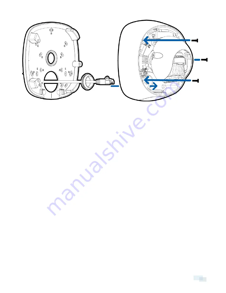
Connecting Cables
Refer to the diagrams in the Overview section for the location of the different connectors.
1. If external input or output devices are part of the installation (for example: door contacts, relays, etc.),
connect the devices to the I/O connector block.
2. If an external microphone needs to be connected to the camera, connect the device to the camera A/V
connector.
For more information, see
Connecting to Microphones, Speakers and Video Monitors
on page 21.
3. (1.0 and 2.0 megapixel models only) If an external video monitor needs to be connected to the camera,
connect the device to the camera A/V connector.
For more information, see
Connecting to Microphones, Speakers and Video Monitors
on page 21.
4. Connect a network cable to the Ethernet Port (RJ-45 connector).
The Link LED will turn on once a network link has been established.
5. Connect power using one of the following methods:
o
Power over Ethernet (PoE) Class 3 — If PoE is available, the LEDs will turn on.
o
External Power — Connect an external 12 V DC or 24 V AC power source to the power connector
block.
6. Check that the Connection Status LED indicates the correct state. For more information, see
LED
Indicators
on page 23.
(Optional) Using the USB Wifi Adapter
If you have a USB Wifi Adapter (H4-AC-WIFI), attach it to the camera's micro USB port to access the camera's
mobile web interface.
After you connect to the wifi signal broadcast by the adapter, you can access the mobile web interface from any
mobile device using the following address:
Connecting Cables
15


