


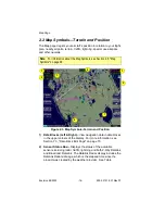


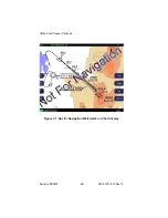


Map Page
Envision EX5000
-20-
600-00151-001 Rev 01
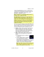
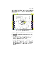
3) Airport Runway Diagrams
—Displays runway layouts of nearby
airports when looking at the map at a less than 5NM range. As
you range in, the scaled runway diagram with heading labels
shows your exact location in proximity to the field.
4) Traffic Indications
—Shows traffic symbol relative to current
position and includes relative altitude (when available) with
respect to airplane symbol. See your traffic sensor User’s Manual
for further details. When available, TIS installations will show a
ground track “stinger” for each intruder, indicating the intruder’s
track as measured by ground radar. Traffic Symbols are shown in
Table 4.1 Traffic Symbols on page 50.
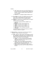
5) Interstate Highways
—Depicted as brown lines when terrain is
selected to be shown. Interstates are labeled in white. (e.g. I-95).
Highways are removed from the terrain map when the range is
greater than 300NM.
2.4
Map Orientation Control
The Map View button allows you to control the orientation of the map
and sensor data displayed on the EX5000. EX5000 traffic and
lightning sensor symbols are positioned relative to the aircraft nose.
When the Map View is North-Up you need to pay more attention to
locate traffic outside the aircraft. Set Map View to Center or Forward
to display this data consistent with typical dedicated traffic and
lightning sensor displays.
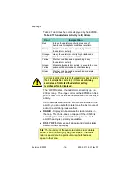
Note
: The Garmin GNS 430/GNC 420 does not differentiate curved
flight path segments from straight segments when interfaced with the
EX5000 via an RS232 interface. Therefore, the EX5000 will connect
the beginning and end waypoints of a curved segment, such as a DME
arc, with a straight line. Under these circumstances, the straight line
must be ignored. Approach procedures should be flown using the GNS
430/GNC 420 navigator’s CDI as the primary reference. Consult your
avionics installation facility to determine if your EX5000 is interfaced to
the GNS 430/GNC420 via ARINC 429 or RS232.
Note
: The Garmin 400W/500W can use the parallel track. For Garmin
400W/500W software at Release 2 or earlier, if a parallel track is active,
the current non-offset leg will be displayed in white. For Garmin 400W/
500W software at Release 3 or later, if a parallel track is active, the
parallel track leg will be displayed in white.
Summary of Contents for Envision EX5000
Page 1: ...600 00151 001 Rev 01 ...
Page 2: ......
Page 8: ...Envision EX5000 vi 600 00151 001 Rev 01 This page intentionally left blank ...
Page 18: ...Introduction Envision EX5000 6 600 00151 001 Rev 01 THIS PAGE INTENTIONALLY LEFT BLANK ...
Page 36: ...Map Page Envision EX5000 24 600 00151 001 Rev 01 ...
Page 46: ...CMax Chart Pages Optional Envision EX5000 34 600 00151 001 Rev 01 ...
Page 58: ...CMax Chart Pages Optional Envision EX5000 46 600 00151 001 Rev 01 ...
Page 73: ...600 00151 001 Rev 01 61 Envision EX5000 THIS PAGE INTENTIONALLY LEFT BLANK ...
Page 74: ...Trip Page Envision EX5000 62 600 00151 001 Rev 01 ...
Page 78: ...Nearest Page NRST Envision EX5000 66 600 00151 001 Rev 01 THIS PAGE INTENTIONALLY LEFT BLANK ...
Page 107: ...Activating Broadcast Datalink Accounts 600 00151 001 Rev 01 95 Envision EX5000 ...
Page 140: ...Envision EX5000 128 600 00151 001 Rev 01 This page intentionally left blank ...
Page 141: ......