5-42
Cruise / Enroute
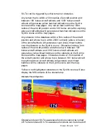
area will not generate any FLTA alerts. Dimensions of the FLTA
runway suppression area are 2.0 nm laterally and 4.0 nm off each
runway end when runway orientations are known or a circle with
a radius of 1 nm centered on the Airfield Reference Point (ARP)
when the on-board databases do not know the runway
orientations. Note that for airfields with multiple runways, this may
have the effect of looking like several irregular shapes around the
airfield. If the aircraft position or the TVV projected impact point
is anywhere within that runway suppression area, no FLTA alert
will be generated. Obstacle threat bubbles can still appear inside
the suppression area.
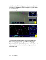
FLTA alerts are inhibited if any of the following conditions are
met:
FLTA is manually turned off via the pilot-accessible Display Setup
tab (generates a “FLTA OFF” annunciation at the top of the
display);
The ownship position is inside the rectangular (or circular in the
case of no known runway orientation) FLTA Inhibit zone depicted
on the 2D map (generates a “FLTA INHIBITED” annunciation at
the top of the display);
The projected ground impact point along track intersects the
terrain inside that FLTA Inhibit rectangle/circle (generates a
“FLTA INHIBITED” annunciation at the top of the display);
The Reduced Terrain Clearance (RTC) violation is projected to
happen inside that FLTA Inhibit rectangle/circle (generates a
“FLTA INHIBITED” annunciation at the top of the display).
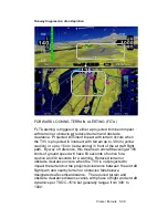
Should a FLTA alert be generated, there are several courses of
action that can be taken and the specific scenario will dictate the
optimum avoidance maneuver. For example, sometimes the best
course of action is to immediately add power and climb, yet
sometimes the best course of action may be a small heading
change, especially in the case of a single obstacle off the nose.
PILOT-SELECTABLE FIELD OF VIEW
The field of view (FOV) depicted on the SynVis scene can be
adjusted at any time by the pilot. SynVis FOV will default to 45
degrees at each power up and can be adjusted using the right-
hand dual concentric knob from 20 degrees to 120 degrees.
Summary of Contents for Entegra
Page 1: ......
Page 2: ......
Page 40: ......
Page 48: ......
Page 92: ......
Page 112: ......
Page 116: ......
Page 117: ...System Alerts 9 1 9 System Alerts 9 2 CAS SYSTEM 9 2 MISCOMPARES 9 6 CROSSCHECK MONITOR 9 8 ...
Page 125: ......
Page 136: ......
Page 150: ......
Page 190: ...D 2 Appendix D SYS Pages MAP MAP TAB ...
Page 191: ...Appendix D SYS Pages D 3 MAP SPLIT TAB ...
Page 192: ...D 4 Appendix D SYS Pages MAP CHART TAB ...
Page 193: ...Appendix D SYS Pages D 5 MAP CHART TAB ...
Page 209: ...Appendix D SYS Pages D 21 ...
Page 210: ...D 22 Appendix D SYS Pages SYS ALERT TAB ...
Page 213: ...Appendix D SYS Pages D 25 SYS SETUP TAB ...
Page 214: ...D 26 Appendix D SYS Pages SYS ICE O2 TAB KC 100 ONLY ...
Page 220: ......
Page 224: ......

