background image

 Replacing the MTS

9

To disconnect the Backlight and Touch-controller cables: 

1

Leaving it connected to the MTS, disconnect the other end of the Backlight cable by doing the following: 

• Making note of the location of its port, disconnect the other end of the Backlight cable from its connection to the GPIO board. 

This cable (7070-30576-00) is connected to port J12 on the GPIO board.

2

Leaving it connected to the MTS, disconnect the other end of the Touch-controller cable by doing the following: 

• Making note of the location of its port, disconnect the other end of the Touch-controller cable from the SBC motherboard. This 

cable (7070-30616-01) is connected to port USB2_9 on Portwell SBCs, port X16 (lower row of pins) on Congatec SBCs, or 
port P24L on Emerson SBCs (refer to 

Figure 12). 

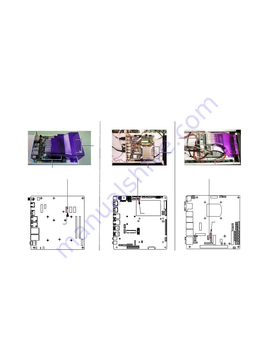
To identify which type of SBC you have: 

Portwell (2022 and later control surfaces) 

The SBC heat sink is mounted closer to the center of the board. In addition, some 

ports are labeled with text and numbers (such as “USB2_9”), and some by port designation (such as “J1”). 

Congatec (2019 and later control surfaces) 

The SBC heat sink is mounted closer to the back of the control surface. Some units 

included a purple plastic shroud, most units did not. 

Emerson (2015 and later control surfaces) 

SBC the heat sink is closer to the front (operator side) of the control surface. All 

units included a plastic shroud. 

3

After disconnecting the cables, use a 9/32 nut driver to remove the screw that secures the LVDS cable to the MTS. 

4

You can now remove the old MTS, pulling the old power and Touch-controller cables out at the same time (make sure cables are 
free of any obstructions). 

5

Proceed to 

Connect and Install the New MTS

.

Figure 12. Portwell model SBC (shown at left), Congatec SBC (center) and Emerson SBC (shown at right)

USB2_9_10

7070-30616-01

X16

7070-30616-01

P24L

7070-30616-01

Congatec

Emerson

Portwell

Summary of Contents for VENUE S6L

Page 1: ...2 Phillips screwdriver 1x 9 32 nut driver or small open end wrench S6L 24C Only Large towel or similar on which to set the MTS S6L 24C only Anti Static wrist strap not included Small cups or other co...

Page 2: ...Prepare the Control Surface Remove the S6L Back Covers all systems Disconnect Light Cables S6L 24C only 2 Remove the MTS Free the MTS from the chassis then disconnect its cables and remove the old MT...

Page 3: ...trol surface by removing the lower and upper back covers The steps required to remove the back cover vary depending on the model of S6L control surface D Series S6L 24D 32D and 48D C Series S6L 24C D...

Page 4: ...scratching the chassis first remove both end caps At minimum one End Cap needs to be loosened enough to let you remove the top cover later in these instructions If you remove either or both of the End...

Page 5: ...Hex driver loosen or remove both the right and left End Caps by loosening the 7 fasteners securing the caps to the chassis At minimum one End Cap needs to be loosened enough to let you remove the top...

Page 6: ...mm Hex driver remove the 4 fasteners that secure the top cover to the control surface 6 Set a large towel or similar across the upper modules of the control surface CKM MTS MLM to protect them 7 Caref...

Page 7: ...ed to Remove the MTS Remove the MTS The MTS must first be freed from the chassis and set face down on the control surface to allow access to the LVDS and other cables To remove the MTS 1 Set a towel b...

Page 8: ...Your replacement MTS includes new Backlight and Touch controller cables pre installed As shown in the following instructions you must detach the LVDS cable from the old MTS then disconnect the Backlig...

Page 9: ...and later control surfaces The SBC heat sink is mounted closer to the center of the board In addition some ports are labeled with text and numbers such as USB2_9 and some by port designation such as...

Page 10: ...nect the LVDS cable to its port on the new MTS 3 in Figure 12 5 Use a 9 32 nut driver to replace the screws that secure each cable to the MTS 6 Proceed to Confirm Installation Confirm Installation To...

Page 11: ...chassis using the fasteners you removed earlier 2 Making sure to orient it correctly re install the upper back cover on the control surface and secure it with the fasteners you re moved earlier refer...

Reviews: