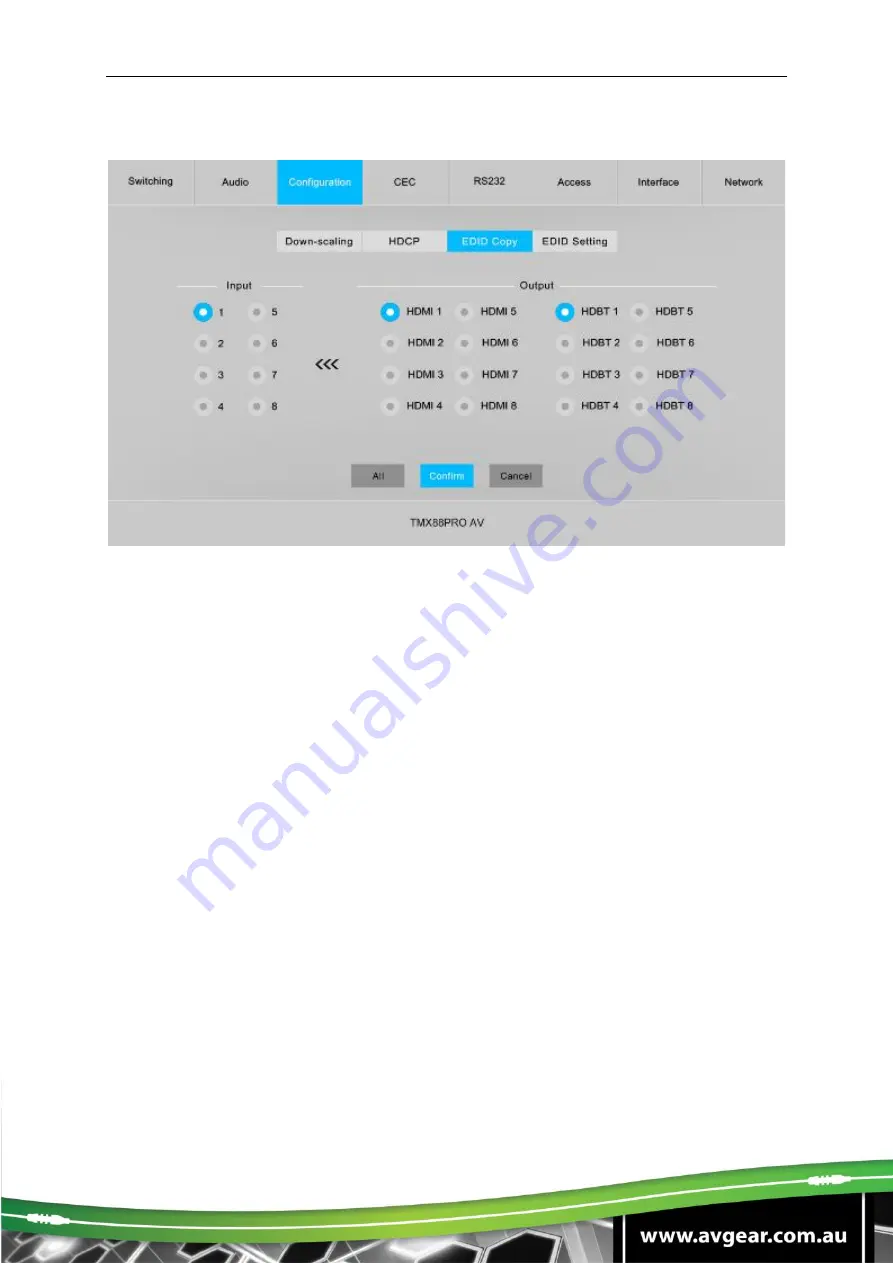
background image

TMX88PRO AV 


6.3.3 EDID Copy 


  Copy the EDID data from a single output port to one or several input ports. 

Operation: 

1) Select one output port. 

2) Select one or several input ports. Press 

ALL 

to select all input ports. 

3) Click 

Confirm

 to save any changes or click 

Cancel

 to cancel any changes that 

have been made. 


Summary of Contents for TMX88PRO AV

Page 1: ...eT cable Transmits a 4K signal up to 40 meters and a 1080p signal up to 70 meters over a single CATx Ethernet cable Volume adjustment for analog L R audio outputs Supports comprehensive EDID management and advanced HDCP management CEC Control The TMX88PRO AV is a professional 8x8 HDMI 2 0 HDBaseT matrix switcher The matrix is an eight input by eight output HDBaseT and HDMI matrix with HDCP 2 2 and...

Page 2: ...on instruction only and is not to be used in a maintenance capacity The functions described in this version are current as at December 2019 Any changes of functions and operational parameters will be updated in future manual versions Please refer to your dealer for the latest product details Version 1 0 20 04 20 ...

Page 3: ... extreme hot or cold temperatures 3 This unit will generate heat during operation please ensure that you allow adequate ventilation to ensure reliable operation 4 Please disconnect the unit from mains power if it will be left unused for a long period of time 5 Please DO NOT try to open the casing of the equipment DO NOT attempt to repair the unit Opening the unit will void the warranty There are h...

Page 4: ...P Address Inquiry 5 7 GUI Control 6 Signal Switching 6 1 Audio Setting 6 2 Configuration 6 3 Down scaling 6 3 1 HDCP Setting 6 3 2 EDID Copy 6 3 3 EDID Setting 6 3 4 CEC Control 6 4 RS232 Control 6 5 Access Setting 6 6 Interface Setting 6 7 Network Settings 6 8 Graphic User Interface Upgrade 6 9 IR Control 7 IR Remote Control 7 1 IR Pass through Control 7 2 Control Local Input Device from Remote 7...

Page 5: ... Device from Remote 8 1 4 RS232 Control Software 8 2 RS232 Commands 8 3 System Setting 8 3 1 Signal Switching 8 3 2 Audio Setting 8 3 3 HDCP Setting 8 3 4 EDID Management 8 3 5 Third party Device Control 8 3 6 CEC Control 8 3 7 Specifications 9 Firmware Upgrade 10 Troubleshooting Maintenance 11 ...

Page 6: ...with computers for monitoring purposes residential video distribution large screen displays conference systems television education banks security institutions etc 1 2 Features 8x8 HDBaseT matrix switcher with built in audio matrix Fully compliant with the HDMI 2 0 and HDCP 2 2 Supports HDMI resolutions up to 4K 60Hz 4 4 4 HDR10 Features eight mirrored HDMI outputs for eight HDBaseT outputs The ei...

Page 7: ...x Mounting Ears with 6 Screws 4x Plastic Cushions with 4 Screws 1x AVGear 12V IR Receiver 1x IR Remote 1x RS232 Cable 3 pin to DB9 16x 3 pin Terminal Blocks 1x Power Cord 1x User Manual Note Please immediately contact your distributor if you find any damage or defect in the components ...

Page 8: ...an IR signal from the IR remote to control the matrix switcher The IR sensor is on the right side of the LED INPUT Eight buttons for input source selection OUTPUT Eight buttons for output channel selection Menu Buttons LOCK Lock or unlock the front panel buttons PRESET Preset setting MENU Menu or confirm button BACK Go back to the previous operation UP Page up DOWN Page down Note Pictures shown in...

Page 9: ...he matrix switcher by the IR remote FW Type A USB port for firmware upgrade TCP IP RJ45 port to connect the control device e g PC to control the matrix switcher by GUI RS232 Eight 3 pin terminal blocks to control the third party devices base on RS232 pass through feature There is a one to one correspondence between the eight RS232 ports and the eight RS232 ports of eight HDBaseT receivers IR IN 1 ...

Page 10: ...al received from the corresponding HDBaseT receivers ALL OUT 3 5mm jack to connect the IR emitter to send the IR signal received from all HDBaseT receivers AC100V 240V Power port to connect an AC 100V 240V power with the power cord GROUND Connect to earth to ensure the unit is well grounded ...

Page 11: ...ed on 4 2 Connection Diagram Tx Rx LINK HDCP Receiver Projector Blu ray Remote IR Emitter IR Receiver Tx Rx LINK HDCP Receiver Projector Blu ray Remote IR Emitter IR Receiver RS232 Tx Rx FW IR EYE TCP IP 1 2 3 4 5 6 7 8 ALL IN 1 2 3 4 5 6 7 8 ALL OUT Tx Rx 1 2 3 4 5 6 7 8 1 2 3 4 5 6 7 8 L R 1 2 3 4 5 6 7 8 HDBaseT HDMI 1 2 3 4 5 6 7 8 1 2 3 4 5 6 7 8 HDMI IR RS232 HDBaseT Ethernet Audio Apply TV ...

Page 12: ... 8 IR OUT ports correspond with 8HDMI INPUTS When you switch an HDMI input the corresponding IR OUT will be switched synchronously Switch an input to several outputs Operation INPUT OUTPUT OUTPUT MENU Example Switch Input 1 to Output 2 3 and 4 Press INPUT 1 Press OUTPUT 2 3 4 Press to confirm 5 2 Panel Button Locking Unlocking Press and hold at least three seconds Press and hold to unlock 5 3 Stat...

Page 13: ...g output port is connected to a display device N means there is no connection between the output port and display device 5 4 EDID Management The Extended Display Identification Data EDID is used by the source device to match its video resolution with the connected display By default the eight source devices invoke the fifth built in EDID 4K 60Hz HDR 2CH Enter EDID management tab Press Press to sel...

Page 14: ... be invoked as shown as below No EDID Video Audio 1 1080p 2CH 2 1080p HDR MultiCH 3 4K 30Hz HDR 2CH 4 4K 60Hz HDR MultiCH 5 Default 4K 60Hz HDR 2CH 6 4K 60Hz HDR MultiCH User Custom Example Input 1 and 2 invoke the built in EDID data 4K 30Hz HDR 2CH Select Built in EDID Press to confirm Press or navigation buttons to select the built in EDID to be invoked Press INPUT 1 and 2 Press to confirm Learn...

Page 15: ...akout Out4 Breakout Out5 Breakout Out6 Breakout Out7 Breakout Out8 Breakout L R OUT 2 L R OUT 3 L R OUT 4 L R OUT 5 L R OUT 6 L R OUT 7 L R OUT 8 SPDIF OUT 1 In1 Breakout In2 Breakout In3 Breakout In4 Breakout In5 Breakout In6 Breakout In7 Breakout In8 Breakout Out1 Breakout Out2 Breakout Out3 Breakout Out4 Breakout Out5 Breakout Out6 Breakout Out7 Breakout Out8 Breakout Out1 ARC Out2 ARC Out3 ARC...

Page 16: ...ol Save the current switching routing to a preset Example Save the current switching routing to preset 2 Press Press and hold at least 3 seconds Press INPUT 2 to select Preset 2 Press to confirm Recall a saved preset Example Recall the saved preset 2 Press Press INPUT 2 to select Preset 2 Press to confirm 5 7 IP Address Inquiry Press Press to select IP Address Press AUDIO Setting IP Address L R OU...

Page 17: ...efault IP settings are IP Address 192 168 0 178 Subnet Mask 255 255 255 0 Type 192 168 0 178 in the internet browser it will enter the below log in webpage Username admin Password admin Type the user name and password and then click Login to enter the section for video switching ...

Page 18: ...e button on the Input 1 row and Output 1 column directs input 1 to output 1 Use the 9 numbered buttons under scene area to save and load layout presets To save a given layout first click one of the numbered buttons then click the Save button To load a previously saved layout first click one of the numbered buttons then click the Recall button ...

Page 19: ...udio sources can be selected for eight analog L R audio output ports and twenty four audio sources can be selected for eight digital SPDIF output ports L R Output Audio Volume Control Adjust L R output audio volume by the volume bar and the three buttons on the right side ...

Page 20: ...g function of HDMI output 1 8 ports When enable down scaling the 4K input can be automatically degraded to 1080p output for compatibility with 1080p display which is connected to the HDMI output port Significiant quality loss may occur with this downscaling conversion and it is not recommended ...

Page 21: ...cally follows the HDCP version of source device Active Default If the input video has HDCP content the HDCP version of HDMI output is HDCP 1 4 for broader video solution If the input video has no HDCP content the HDMI output has no HDCP too Click Confirm to save any changes or click Cancel to cancel any changes that have been made ...

Page 22: ... a single output port to one or several input ports Operation 1 Select one output port 2 Select one or several input ports Press ALL to select all input ports 3 Click Confirm to save any changes or click Cancel to cancel any changes that have been made ...

Page 23: ...a built in EDID 2 Select one or several input ports Press ALL to select all input ports 3 Click Confirm to save setting Upload user defined EDID by the below steps 1 Prepare the EDID file bin on the control PC 2 Select the User defined 3 Click the box and then select the EDID file bin according the tooltip 4 Click Apply to upload the user defined EDID and then click Confirm to save setting ...

Page 24: ...vices HDBaseT output devices and local HDMI output devices support CEC they can be controlled via the following CEC interface 1 Input Source Device Control Select one or several HDMI input source devices to be controlled and then press function buttons ...

Page 25: ...evice Control Select one or several HDBaseT output devices to be controlled and then press function buttons 3 HDMI Output Device Control Select one or several HDMI output devices to be controlled and then press function buttons ...

Page 26: ...ort which is connected to HDBaseT receiver which must have third party device attached 2 Set the baud rate 3 Typing the commands in the box to control the selected remote third party device which is connected to HDBaseT receiver If click the Hex the RS232 commands can be typed with hexadecimal value 4 Click Send to transmit RS232 command to the selected HDBaseT port ...

Page 27: ...ccess Setting Reset the login admin and user password Lock or unlock the front panel buttons Get the GUI and firmware version Click Confirm to save any changes or click Cancel to cancel any changes that have been made ...

Page 28: ...TMX88PRO AV 6 7 Interface Setting Modify title bar label LCD readout and button labels Click Confirm to save any changes or click Cancel to cancel any changes that have been made ...

Page 29: ...MX88PRO AV 6 8 Network Settings Static IP or Dynamic Host Configuration Protocol DHCP Modify the static IP Address Subnet Mask and Gateway ...

Page 30: ...name and password the same as the GUI log in setting modified password will be available only after rebooting to login the configuration interface After that click Administration in the source menu to get to Upload Firmware as shown below Select the update file and click Apply button and then it will start upgrade process ...

Page 31: ...selection buttons Menu buttons ALL Select all inputs or all outputs EDID Enable one or several input sources to manually capture and learn the EDID data of output device CLEAR Cancel the current operation if ENTER has not been pressed ENTER Confirm the desired operation Note The IR receivers which are connected to HDBaseT receivers can also receive IR signals from the IR remote so the matrix switc...

Page 32: ... Control local input device through IR OUT port Example Switch HDMI input 3 to HDBaseT output 4 Connect an IR receiver to IR IN port on the receiver then connect an IR emitter to the IR OUT 3 on the matrix switcher The third input source can be controlled through its corresponding IR output port The connection diagram is shown below RS232 Tx Rx FW IR EYE TCP IP 1 2 3 4 5 6 7 8 ALL IN 1 2 3 4 5 6 7...

Page 33: ...cted HDBaseT receiver as shown in the diagram below RS232 Tx Rx FW IR EYE TCP IP 1 2 3 4 5 6 7 8 ALL IN 1 2 3 4 5 6 7 8 ALL OUT Tx Rx 1 2 3 4 5 6 7 8 1 2 3 4 5 6 7 8 L R 1 2 3 4 5 6 7 8 HDBaseT HDMI 1 2 3 4 5 6 7 8 1 2 3 4 5 6 7 8 Tx Rx LINK HDCP Receiver Display Blu Ray Remote IR Receiver Tx Rx LINK HDCP Receiver Display Blu Ray Remote IR Receiver Tx Rx LINK HDCP Receiver Display Blu Ray Remote I...

Page 34: ... Connect an IR receiver to IR IN 3 port on the matrix switcher then connect an IR emitter to the IR OUT on the receiver as shown in the diagram below Tx Rx LINK HDCP Receiver Display IR Emitter RS232 Tx Rx FW IR EYE TCP IP 1 2 3 4 5 6 7 8 ALL IN 1 2 3 4 5 6 7 8 ALL OUT Tx Rx 1 2 3 4 5 6 7 8 1 2 3 4 5 6 7 8 L R 1 2 3 4 5 6 7 8 HDBaseT HDMI 1 2 3 4 5 6 7 8 1 2 3 4 5 6 7 8 4K Blu Ray HDMI IR HDBaseT ...

Page 35: ...aseT receiver as shown in the diagram below RS232 Tx Rx FW IR EYE TCP IP 1 2 3 4 5 6 7 8 ALL IN 1 2 3 4 5 6 7 8 ALL OUT Tx Rx 1 2 3 4 5 6 7 8 1 2 3 4 5 6 7 8 L R 1 2 3 4 5 6 7 8 HDBaseT HDMI 1 2 3 4 5 6 7 8 1 2 3 4 5 6 7 8 Tx Rx LINK HDCP Receiver IR Emitter Tx Rx LINK HDCP Receiver IR Emitter Tx Rx LINK HDCP Receiver IR Emitter Tx Rx LINK HDCP Receiver IR Emitter 4K Blu Ray IR Receiver Display Re...

Page 36: ...cher from a local PC the 3 pin to DB9 RS232 Cable is used to connect between the matrix and PC The connection diagram is shown below RS232 Tx Rx FW IR EYE TCP IP 1 2 3 4 5 6 7 8 ALL IN 1 2 3 4 5 6 7 8 ALL OUT Tx Rx 1 2 3 4 5 6 7 8 1 2 3 4 5 6 7 8 L R 1 2 3 4 5 6 7 8 HDBaseT HDMI 1 2 3 4 5 6 7 8 1 2 3 4 5 6 7 8 PC RS232 ...

Page 37: ...enable or disable this control mode For example send the command RS232RCM00ON to enable the remote control mode for all HDBaseT outputs and send the command RS232RCM00OFF to disable the remote control mode for all HDBaseT outputs Please refer to the 8 3 1 System Control for more details RS232 Tx Rx FW IR EYE TCP IP 1 2 3 4 5 6 7 8 ALL IN 1 2 3 4 5 6 7 8 ALL OUT Tx Rx 1 2 3 4 5 6 7 8 1 2 3 4 5 6 7 ...

Page 38: ... Cable then connect a third party device e g projector to the RS232 port of the determined HDBaseT receiver The remote third party device can be controlled by the local PC the connection diagram is shown below RS232 Tx Rx FW IR EYE TCP IP 1 2 3 4 5 6 7 8 ALL IN 1 2 3 4 5 6 7 8 ALL OUT Tx Rx 1 2 3 4 5 6 7 8 1 2 3 4 5 6 7 8 L R 1 2 3 4 5 6 7 8 HDBaseT HDMI 1 2 3 4 5 6 7 8 1 2 3 4 5 6 7 8 PC 4K Blu R...

Page 39: ...32 Cable then connect a third party device e g projector to the RS232 port of matrix switcher The local third party device can be controlled by the remote PC the connection diagram is shown below PC Tx Rx LINK HDCP Tx Rx LINK HDCP Receiver Display RS232 Tx Rx FW IR EYE TCP IP 1 2 3 4 5 6 7 8 ALL IN 1 2 3 4 5 6 7 8 ALL OUT Tx Rx 1 2 3 4 5 6 7 8 1 2 3 4 5 6 7 8 L R 1 2 3 4 5 6 7 8 HDBaseT HDMI 1 2 3...

Page 40: ... using CommWatch exe as an example The icon is shown below Double click the icon to run and its interface is depicted below Please set the parameters of COM number bound rate data bit stop bit and the parity bit correctly and then you are able to send command in command sending area Parameter configuration area Monitoring area show the commands and its feedback information Command sending area ...

Page 41: ...IP to xxx xxx xxx xxx SetGuiIP 192 168 0 17 6 SetGuiIP 192 168 0 17 6 Baudrate115200 Set the serial baud rate of matrix switcher to 115200 Set Local RS232 Baudrate Is 115200 Baudrate57600 Set the serial baud rate of matrix switcher to 57600 Set Local RS232 Baudrate Is 57600 Baudrate38400 Set the serial baud rate of matrix switcher to 38400 Set Local RS232 Baudrate Is 38400 Baudrate19200 Set the se...

Page 42: ...rol MCU ON RS232 Remote 02 Control MCU ON RS232 Remote 08 Control MCU ON RS232RCM XX OFF Disable the RS232 remote control mode for HDBT output XX that the matrix switcher cannot be controlled from remote PC XX 00 08 The XX 00 represents all HDBT outputs RS232RCM00OFF RS232 Remote 01 Control MCU OFF RS232 Remote 02 Control MCU OFF RS232 Remote 08 Control MCU OFF STA_RS232RCM Report the RS232 remote...

Page 43: ...ontrol MCU ON IR Remote 02 Control MCU ON IR Remote 08 Control MCU ON OUT XX Turn on output XX XX 00 16 The XX 00 represents all outputs XX 01 08 represents HDBT output 1 8 XX 09 16 represents HDMI output 1 8 OUT00 Turn ON Output 01 Turn ON Output 02 Turn ON Output 16 OUT XX Turn off output XX XX 00 16 The XX 00 represents all outputs XX 01 08 represents HDBT output 1 8 XX 09 16 represents HDMI ou...

Page 44: ...ption Command Example and Response IRFVON Enable the IR switching to follow the video switching IR Follow Video ON IRFVOFF Disable the IR switching to follow the video switching IR Follow Video OFF OUT XX YY Switch video input YY to video output XX XX 00 08 YY 01 08 The XX 00 represents all outputs OUT01 04 Output 01 Switch To In 04 STA_VIDEO Report the input channel for all outputs Output 01 Swit...

Page 45: ... Save Success Preset 01 Sta Out 01 In 01 Out 02 In 02 Out 08 In 08 PresetRecall XX Recall present XX XX 01 09 PresetRecall02 Preset 02 Recall Output 01 Switch To In 02 Local 02 IR Out Switch To Remote 01 IR IN Output 02 Switch To In 02 Local 02 IR Out Switch To Remote 02 IR IN Output 03 Switch To In 02 Local 02 IR Out Switch To Remote 03 IR IN Output 04 Switch To In 02 Local 02 IR Out Switch To Re...

Page 46: ...6 Breakout 18 Out2 ARC 07 In7 Breakout 19 Out3 ARC 08 In8 Breakout 20 Out4 ARC 09 Out1 Breakout 21 Out5 ARC 10 Out2 Breakout 22 Out6 ARC 11 Out3 Breakout 23 Out7 ARC 12 Out4 Breakout 24 Out8 ARC SPDIF01 04 SPDIF Out 01 Switch To Video In 04 STA_SPDIF Report SPDIF audio status SPDIF Out 01 Switch To Video In 01 SPDIF Out 02 Switch To Video In 02 SPDIF Out 08 Switch To Video In 08 AVOLUME XX Y Y Set...

Page 47: ...g L R audio output XX XX 00 08 The XX 00 represents all L R audio outputs YY 01 16 Y Y Audio Source YY Audio Source 01 In1 Breakout 09 Out1 Breakout 02 In2 Breakout 10 Out2 Breakout 03 In3 Breakout 11 Out3 Breakout 04 In4 Breakout 12 Out4 Breakout 05 In5 Breakout 13 Out5 Breakout 06 In6 Breakout 14 Out6 Breakout 07 In7 Breakout 15 Out7 Breakout 08 In8 Breakout 16 Out8 Breakout ANALOG01 04 Analog O...

Page 48: ...omatically follows the HDCP version of source device XX 00 16 XX 00 represents all outputs XX 01 08 represents HDBT output 1 8 XX 09 16 represents HDMI output 1 8 HDCP00pAS OUT 01 HDCP PASSIVE OUT 02 HDCP PASSIVE OUT 15 HDCP PASSIVE OUT 16 HDCP PASSIVE HDCP XX BYP Set the HDCP mode of output XX to Active If the input video has HDCP content the HDCP version of HDMI output is HDCP 1 4 for broader vi...

Page 49: ...MX88PRO AV OUT 15 HDCP BYPASSS OUT 16 HDCP BYPASSS ...

Page 50: ...sending command to ensure the data can be received successfully EDIDUpgrade01 EDIDUpgradeU 256 9600bps Input XX User Define EDID Upgrade OK By RS232 Or GUI EDID XX YY The input XX recall the embedded EDID YY XX 00 08 The 00 represents all inputs YY 01 07 YY EDID 01 1080p 2CH 02 1080p MultiCH 03 4K 30Hz HDR 2CH 04 4K 30Hz HDR MultiCH 05 4K 60Hz HDR 2CH 06 4K 60Hz HDR MultiCH 07 User defined EDID ED...

Page 51: ...xx ASCII string The X 1 7 represents the baud rate of third party device X 1 the baud rate is 2400 X 2 the baud rate is 4800 X 3 the baud rate is 9600 X 4 the baud rate is 19200 X 5 the baud rate is 38400 X 6 the baud rate is 57600 X 7 the baud rate is 115200 The YY 00 represents all HDBT outputs The YY 01 08 represents the HDBT output 1 8 3 01 123456 Send the ASCII command 123456 to the far end t...

Page 52: ...xx When power off the matrix switcher automatically send ASCII command xxx to power off far end third party device xxx ASCII string The X 1 7 represents the baud rate of third party device X 1 the baud rate is 2400 X 2 the baud rate is 4800 X 3 the baud rate is 9600 X 4 the baud rate is 19200 X 5 the baud rate is 38400 X 6 the baud rate is 57600 X 7 the baud rate is 115200 The YY 00 represents all...

Page 53: ...sents the specific command from the table below Control the input source Command Description Command Example and Response CECI AA BB CC 00 Confirm operation Enter CECI02044400 CEC Input 02 Send Success CECI AA BB CC 01 UP direction CECI01044401 CEC Input 01 Send Success CECI AA BB CC 02 DOWN direction CECI01044402 CEC Input 01 Send Success CECI AA BB CC 03 LEFT direction CECI03044403 CEC Input 03 ...

Page 54: ...C 41 Volume up CECO05404441 CEC Output 05 Send Success CECO AA BB CC 42 Volume down CECO05404442 CEC Output 05 Send Success CECO AA BB CC 43 Mute CECO05404443 CEC Output 05 Send Success CECO AA BB 04 Power on CECO038004 CEC Output 03 Send Success CECO AA BB 36 Power off CECO038036 CEC Output 03 Send Success ...

Page 55: ...upports 44 1KHz 48KHz 96KHz ARC Audio Sampling Rate Supports 48KHz 96KHz Frequency Response 20Hz 20KHz 3dB Audio Output Impedance 70Ohms Max Input Level L R 2 0Vrms 0 5dB 2V 16dB headroom above 10dBV 316mV nominal consumer line level signal SPDIF 0 05dBFS THD N 0 05 80dB 20Hz 20KHz bandwidth 1KHz sine at 0dBFS level or max level SNR L R 80dB 20Hz 20KHz bandwidth SPDIF 90dB 20Hz 20 kHz bandwidth Cr...

Page 56: ...blocks 1 Type A USB 1 RJ45 General Transmission Mode HDBaseT Transmission Distance 1080p 230 feet 70 meters 4K 60Hz 131 feet 40 meters Bandwidth 18Gbps Operation Temperature 5 55 Storage Temperature 25 70 Relative Humidity 10 90 External Power Supply 100V 240V AC 50 60Hz Power Consumption 125W Max Dimension W H D 436 6mm x 88mm x 440mm Net Weight 5 8kg ...

Page 57: ...ile named of READY TXT would be showed 5 Directly copy one of two upgrade files e g 08010000 APP to the BOOTDISK U disk 6 Reopen the U disk to check the filename READY TXT whether automatically becomes SUCCESS TXT if yes the firmware was updated successfully otherwise the firmware updating is fail the name of upgrade file should be confirm again and then follow the above steps to update again 7 Re...

Page 58: ...wer cord connection is secure EDID management does not work normally The HDMI cable is broken at the output end Replace with an HDMI cable which is in good working condition Static discharge when connecting the video connectors Poor grounding Check the grounding and make sure it is connected well Cannot control the device by control device e g a PC through RS232 port Wrong RS232 communication para...

Reviews: