background image

Model 6700 Family User’s Manual

10

There are three modes available to you with
Switch 1 in the Menu


mode or OPEN


position.

They are as follows:

DIAG (Diagnostic Mode) 

– To test areas of

the scale’s function

CAL (Calibration Mode) 

– To calibrate the

scale

CONF (Configuration Mode) 

– To config-

ure the scale for your application

The structure for these menus is shown in
Figure 3. Specific information about each mode
followed by step-by-step instructions for access-
ing them are described in the following pages.

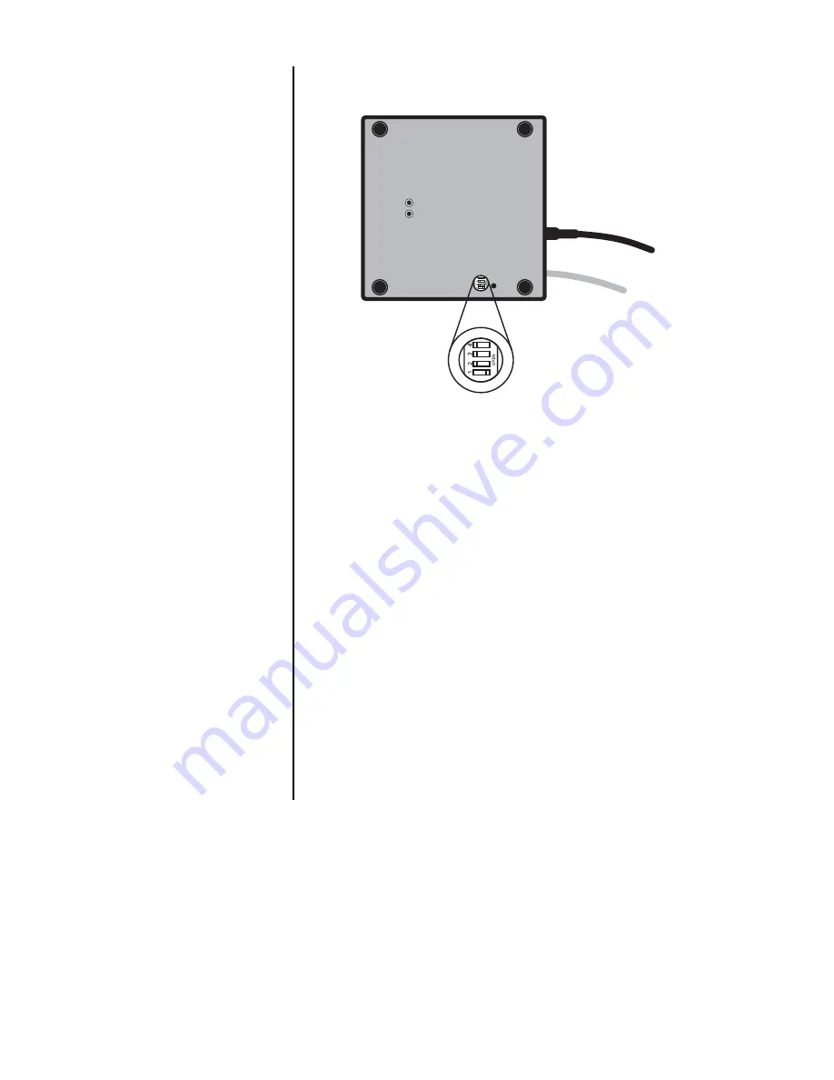
Figure 2

Bottom view

Menu Mode

Bottom View of 6702 or 6710 Scale

Summary of Contents for 6700

Page 1: ...User s Manual Model 6700 Family Model 6720 Model 6702 Model 6710 Point of Sale Interface Scales ...

Page 2: ...ical shock Do not remove cover No user serviceable parts inside Refer servicing to qualified service personnel Avery Berkel reserves the right to change specifications at any time CAUTION October 2009 6700_u_en_7424_14787 p65 Issue AJ Printed in USA ...

Page 3: ...fications 4 Initial Setup 7 Operation 8 Menu Structure 11 Diagnostics Mode 13 Configuration Mode 17 Calibration Mode 19 Review Test Scale Settings 21 Communication 22 Error Codes 23 Troubleshooting 24 Spare Parts Listing 26 Table of Contents ...

Page 4: ...aced with a cash register computer or other POS terminal Important Weights and Measures normally requires inspection of scale before scale is placed into operation Model Capacity lb Capacity kg 6702 7 15 x 005 7 x 002 6702 15 30 x 01 15 x 005 6710 7 15 x 005 7 x 002 6710 15 30 x 01 15 x 005 6720 7 15 x 005 7 x 002 6720 15 30 x 01 15 x 005 6720 30 60 x 02 30 x 01 6720 60 120 x 05 60 x 02 Model 6702...

Page 5: ...tion Adjustable center and side stops Model 6720 Die cast aluminum base with a stainless steel weigh platter Overload protection Adjustable center stop fixed corner stops high six digit LCD Key panel with ZERO and TEST keys Remote display with 7 ft cable Standard on Models 6702 and 6710 optional on 6720 Using the leveling bubble as a guide adjust the four adjustable feet to level the scale Initial...

Page 6: ...th a lead wire or pressure sensitive security seal The remote or primary indicators have no metrological features that require the use of a security seal The scale has 100 000 internal counts The time interval when weight is applied to the scale until a stable weight is displayed 0 1000d 1 5 seconds 1000d 2 0 seconds maximum mean average Factory default settings 9600 baud 7 data bits even parity 1...

Page 7: ... use the dimensions on the following page to guide construction Scale Dimensions Min Cut Out Dimensions D 10 4 in 26 4 cm 11 1 in 28 2 cm W 6 4 in 16 3 cm 7 1 in 18 0 cm H 2 5 in 6 35 cm Adjustable to 3 0 in 7 6 cm Scale Dimensions Min Cut Out Dimensions D 10 4 in 26 4 cm 11 1 in 28 2 cm W 10 4 in 26 4 cm 11 1 in 28 2 cm H 2 5 in 6 35 cm Adjustable to 3 0 in 7 6 cm Scale Dimensions Min Cut Out Dim...

Page 8: ...scale can support more than one display however only one keypad is operable Switch 3 selects internal or external display keypad operation Switch 3 Settings Closed internal display keys operational Open external display keys operational The normal setting for the 6720 with the internal display is Switch 3 Closed On 6720 w remote only or 6710 and 6702 scales Switch 3 Open When the scale is first po...

Page 9: ... The TEST key can be used to perform the initial power up test sequence recall diagnostic routines or to view the scale configuration information This key also acts as YES or ACCEPT in the Menu mode The 6700 models power up ready for weighing operations Access the Menu mode by setting Switch 1 shown in Figure 1 or 2 to the OPEN or Menu mode position Top View of 6720 Scale with Platter Removed Perf...

Page 10: ...the scale s function CAL Calibration Mode To calibrate the scale CONF Configuration Mode To config ure the scale for your application The structure for these menus is shown in Figure 3 Specific information about each mode followed by step by step instructions for access ing them are described in the following pages Figure 2 Bottom view Menu Mode Bottom View of 6702 or 6710 Scale ...

Page 11: ...Model 6700 Family User s Manual 11 Figure 3 Menu Structure ...

Page 12: ...ed capacity Alternative Capacity Calibration Weights 9 995 lb 10 lb 15 x 005 lb 10 15 lb 7 x 002 kg 7 kg 9 995 kg 10 kg 30 x 01 lb 10 20 30 lb 15 x 005 kg 10 15 kg 60 x 02 lb 10 30 60 lb 30 x 01 kg 10 20 30 kg 99 x 05 lb 10 50 100 lb 120 x 05 lb 10 50 100 lb 60 x 02 kg 10 30 60 kg Display Baud Parity 12 E 1200 Even 24 E 2400 Even 48 E 4800 Even 96 E 9600 Even 19 2 E 19 2K Even 12 o 1200 Odd 24 o 2...

Page 13: ...d back into the receive channel and verified against what was sent Requires a jumper short between transmit and receive data lines DIVISION TEST w AZT DIV A Weight data is normalized to 100 000 counts of displayed resolution AZT Auto Zero Tracking is enabled DIVISION TEST w o AZT DIV N Weight data is normalized to 100 000 counts of dis played resolution AZT is disabled Viewable configuration setti...

Page 14: ... 1 or 2 DIAG is displayed 2 Press the TEST key DISP is displayed This stands for display 3 Press the TEST key to perform the display test described earlier Display test is performed and the display shows DISP after the test is completed 4 Press the ZERO key RA is displayed This stands for the RAM test 5 Press the TEST key to perform the RAM test PASS or FAIL is displayed briefly then RA 6 Press th...

Page 15: ...This stands for the high resolution DIVISION TEST w o AZT enabled 14 Press the TEST key to perform this test The display shows the weight on the scale at a resolution of 100 000 counts 15 Press the TEST key to stop the test DIV N is displayed 16 Press the ZERO key LN FR is displayed This stands for line frequency 17 Press the TEST key The current line frequency 50 or 60 is displayed DIAG will flas...

Page 16: ...ocol selection is displayed 20 Press the ZERO key BAUD is displayed This stands for baud rate 21 Press the TEST key The current baud rate and parity selec tion is displayed 22 Press the ZERO key CAP is displayed This stands for capacity 23 Press the TEST key The current capacity resolution selection is displayed 24 Press the ZERO key UNITS is displayed This stands for unit of measure 25 Press the ...

Page 17: ...ible 8213 8213 compatible Sharp 2250 2250 compatible Swintec TEC MA 1535 1595 compatible TEC ATT AT T compatible o4000 Olympia Cash Register compatible Approved for use with 30 and 60 lb or 7 15 30 and 60 kg capacities only Access the Menu mode as shown in Figure 3 1 From the DIAG display press the ZERO key until CONF is displayed or from the normal weighing mode move Switch 1 to the Menu mode or ...

Page 18: ...isplayed 6 Press the TEST key The current baud and parity choice is displayed 7 Use the ZERO key to scroll the choices found in Table 2 When the choice you want is displayed press the TEST key The choice is accepted and the display shows the BAUD item 8 Press the ZERO key until PROT is displayed 9 Press the TEST key The current RS 232 communication protocol is displayed 10 Press the ZERO key to sc...

Page 19: ... normal weighing mode move Switch 1 to the Menu mode or OPEN position Press the ZERO key until CAL is displayed 2 Press the TEST key 50 H or 60 H is displayed This is the AC line frequency 3 Press the ZERO key to toggle between the choices When the choice you want is displayed press the TEST key That choice is accepted and LBS or 1000Gr is displayed 4 Press the ZERO key to toggle between the choic...

Page 20: ...n weights on the scale and press the TEST key After a brief wait DONE is displayed 8 Remove all calibration weights from scale 9 Press the TEST key DIAG is displayed or return Switch 1 to the closed position The scale returns to normal weighing mode The scale is now tested configured and cali brated It is ready for use in your application The capacity selected must correlate with the rated capacit...

Page 21: ...view the current system settings press and hold the TEST until the display shows dashes _ _ _ _ Release the TEST key and the display will prompt DISP and the scale is now in the Review Test Mode Press the ZERO key to move to the next item in the menu Press the TEST key to select the displayed item to run or view When finished running tests or viewing the settings press the ZERO key until DONE is d...

Page 22: ... duplex asynchronous or smart device for output of weight data to an ECR device The 6700 9 pin style is capable of RS 232 communication only Serial commands will be responded to only when the scale is in the normal operating mode and Switch 1 on the main board is in the CLOSED position Baud Rates 1200 2400 4800 9600 or 19 2K Word Length 10 Bits 1 Start 7 Data 1 Parity 1 Stop Parity Even Odd or Non...

Page 23: ...T 4 JMP 1 4 DTR OUT 5 SG 5 GRD 6 JMP 1 6 DSR IN 7 JMP 2 7 RTS OUT 8 JMP 2 8 CTS IN 9 NC 9 RI IN Any system errors detected by the scale will be displayed as the letter E followed by a two digit error code Press the TEST key to continue operation If a calibration error occurs the only way to clear it is by recalibrating the scale The error codes are broken down into two hexadecimal numbers with eac...

Page 24: ...board 4 Replace the main board Missing or extra segments on display 1 Replace the display board 2 Replace the main board Scale will not return to zero or incorrect weight is displayed 1 Press the ZERO key 2 Check for interference of weighing platform 3 Power down remove all items from the platter and then power up the scale 4 Recalibrate the scale 5 Replace the load cell 6 Replace the main board T...

Page 25: ... then power up the scale 4 Recalibrate the scale 5 Replace the load cell 6 Replace the main board Display shows center _ _ _ _ dashes Indicates that the scale is outside zero capacity of 2 1 Verify that weigh platter is on the scale 2 Press the ZERO key 3 Power down remove any items from the platter and then power up the scale 4 Recalibrate the scale 5 Replace the load cell 6 Replace the main boar...

Page 26: ... Replace the display PCB 4 Replace the display cable 5 Replace the main PCB DESCRIPTION PART NUMBER Keyboard Panel 56143 0018 Display PCB 7405 15465 RS 232 PCB 7405 14704 2 Power Supply 6702 6710 1148 15535 Power Supply 6720 1148 15536 RS 232 Cable PC 1140 13842 6700 7 Kg 15 lb Loadcell 7154 16323 07 6700 15 Kg 30 lb Loadcell 7154 16323 15 6700 30 Kg 60 lb Loadcell 7154 16323 30 6700 60 Kg 120 lb ...

Page 27: ...Model 6700 Family User s Manual 27 ...

Page 28: ...Avery Berkel North America 1000 Armstrong Drive Fairmont MN 56031 PH Toll Free 800 237 1886 FAX Toll Free 800 237 2063 sales AveryBerkelUSA com www AveryBerkelUSA com ...

Reviews: