


8
1.0 Introduction
AVerMedia AVerAI EN713-AAE9 is a fully featured carrier board developed for NVIDIA
®
Jetson Nano/ Xavier NX
module (EN713/NX213B). It is specifically designed to have eight 1
0/100Mb Ethernet ports with PoE (PSE,
Power Sourcing Equipment) support.
Operating with
NVIDIA
®
Jetson Nano/ Xavier NX
module, EN713-AAE9/EN713/NX213B can process eight
channels of 1080p30 video stream, which makes it the perfect choice in building the high performance AI edge
computing platform for the intelligent video analytics applications.
EN713-AAE9/ EN713/ NX213B have compact size, which can fit in the compact platform for the commercial and
industrial application. And it can operate in the temperature range from -10°C up to 70°C.
AVerAI
EN713-AAE9/ EN713/ NX213B provides not only the access to a great list of latest interfaces on Nano/ Xavier NX
module but also 1x RS-485 interface, 1x micro controller unit (MCU), and 1x RTC battery as the function
enrichment.
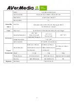
1.1 Product Specifications
Product Name
Fanless/Fan/Carrier Board
Fanless Box PC
EN713/ NX213B
Carrier Board
EN713-AAE9
Core
System on Module (SoM)
Equips NVIDIA® Jetson Nano™/ Xavier NX module
Fully support NVIDIA®
Jetson Nano™/ Xavier NX
module
Front I/O
HDMI 2.0 Output
1x HDMI 2.0a/b Type-A supports maximum resolution 3840x2160 at 60Hz
USB 2.0
1x USB 2.0 Micro-B for recovery
USB 3.0
2x USB 3.0 Type-A
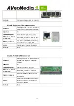
10/100/1000 BASE-T
Ethernet
1x GbE RJ-45
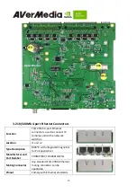
8 ports PoE (8x 10/100 MbE RJ-45 PSE, Power Sourcing Equipment, IEEE 802.3 AT/AF
with power budget)
SATA Rev. 3.0
1x
Audio
1x Mic-in, 1x Speaker-out
Summary of Contents for AVerAI EN713
Page 5: ...5 AVerMedia Global Offices https www avermedia com professional contact ...
Page 10: ...10 2 0 Product Overview 2 1 Block Diagram ...
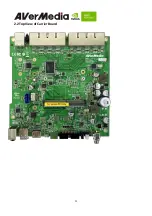
Page 11: ...11 2 2 Top View of Carrier Board ...
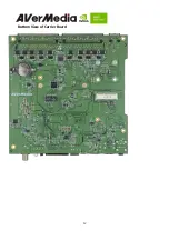
Page 12: ...12 Bottom View of Carrier Board ...
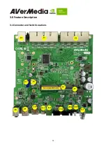
Page 14: ...14 3 0 Feature Description 3 1 Connector and Switch Locations ...


