


13
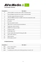
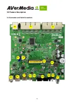
2.3 Connector Summary
Designation
Description
J1
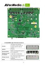
RJ45 1
0/100Mb
4-port Ethernet connector with POE support
J2
RJ45 1
0/100Mb
4-port Ethernet connector with POE support
J3
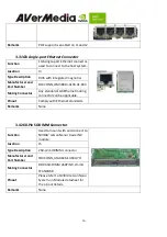
RJ45 1G
b
single-port Ethernet connector
J5
260-pin SODIMM connector for NVIDIA
®
Jetson Nano/ Xavier NX module
J6
SATA power wafer
J7
Fan wafer
J8
Mic and speaker connector
J9
USB 3.1 Gen 1 2-port connector with 900mA x2
J10
HDMI video output connector
J11
USB/OTG micro-type connector
J12
RS-485 connector
J13
54VDC power Jack
J14
20-pin header UART console for debug, I2C, GPIO
J16
Mini card for USB only
J17
SATA connector
BT1
RTC battery connector
2.4 Switch Summary
Designation
Description
SW8
Force recovery button
SW9
Power on button
SW10
4-pin DIP switch with four sets of setting as defi
ned in Section 3.20.
Summary of Contents for AVerAI EN713
Page 5: ...5 AVerMedia Global Offices https www avermedia com professional contact ...
Page 10: ...10 2 0 Product Overview 2 1 Block Diagram ...
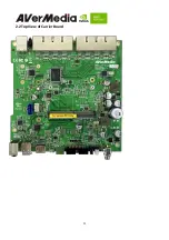
Page 11: ...11 2 2 Top View of Carrier Board ...
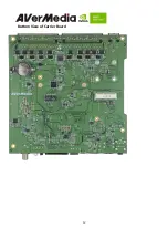
Page 12: ...12 Bottom View of Carrier Board ...
Page 14: ...14 3 0 Feature Description 3 1 Connector and Switch Locations ...


