background image


FCC NOTICE (Class A) 

This device complies with Part 15 of the FCC Rules. Operation is subject to the following 

two  conditions:  (1)  this  device may  not  cause  harmful  interference, and  (2)  this  device 

must accept any interference received, including interference that may cause undesired 

operation. 

Federal Communications Commission Statement 

NOTE- This equipment has been tested and found to comply with the limits for a Class A digital device, 

pursuant  to  Part  15  of  the  FCC  Rules.  These  limits  are  designed  to  provide  reasonable  protection 

against  harmful  interference  in  a  residential  installation.  This  equipment  generates  uses  and  can 

radiate radio frequency energy and, if not installed and used in accordance with the instructions, may 

cause harmful interference to radio communications. However, there is no guarantee that interference 

will not occur in a particular installation. If this equipment does cause harmful interference to radio or 

television  reception,  which  can  be  determined  by  tuning  the  equipment  off  and  on,  the  user  is 

encouraged to try to correct the interference by one or more of the following measures:   

  Reorient or relocate the receiving antenna. 

  Increase the separation between the equipment and receiver.   

  Connect  the  equipment  into  an  outlet  on  a  circuit  different  from  that  to  which  the  receiver  is 

connected. 

  Consult the dealer or an experienced radio/television technician for help.   

Class A ITE 

Class A ITE is a category of all other ITE which satisfies the class A ITE limits but not the class B ITE 

limits. Such equipment should not be restricted in its sale but the following warning shall be included in 

the instructions for use: 


European Community Compliance Statement (Class A) 

This product is herewith confirmed to comply with the requirements set out in the Council 

Directives  on  the  Approximation  of  the  laws  of  the  Member  States  relating  to 

Electromagnetic Compatibility Directive 2014/30/EU. 


Warning 

-This  is  a  class  A  product.  In  a  domestic  environment  this  product  may  cause  radio 

interference in which case the user may be required to take adequate measures.


DISCLAIMER 

No warranty or representation, either expressed or implied, is made with respect to the contents of this 

documentation, its quality, performance, merchantability, or fitness for a particular purpose. Information 

presented in this documentation has been carefully checked for reliability; however, no responsibility is 

assumed  for  inaccuracies.  The  information  contained  in  this  documentation  is  subject  to  change 

without notice. 

In no event will AVer Information Inc. be liable for direct, indirect, special, incidental, or consequential 

damages arising out of the use or inability to use this product or documentation, even if advised of the 

possibility of such damages.


Summary of Contents for CAM520

Page 1: ...CAM520 User Manual ...

Page 2: ...ent from that to which the receiver is connected Consult the dealer or an experienced radio television technician for help Class A ITE Class A ITE is a category of all other ITE which satisfies the class A ITE limits but not the class B ITE limits Such equipment should not be restricted in its sale but the following warning shall be included in the instructions for use European Community Complianc...

Page 3: ...ry Safety Information Store batteries in a cool and dry place Do not throw away used batteries in the trash Properly dispose used batteries through specially approved disposal methods Remove the batteries if they are not in use for long periods of time Battery leakage and corrosion can damage the remote control Dispose of batteries safely and through approved disposal methods Do not use old batter...

Page 4: ...ra 2 Remote Control 3 Setup CAM520 5 Device Connection 5 Wall Mount Installation 6 Use CAM520 9 Make a Video Call 9 LED Indicator 9 AVer PTZApp 10 Install AVer PTZApp 10 Use AVer PTZApp 10 Select Remote Control 16 Set the Camera Number 17 Hotkey Control 18 ...

Page 5: ...nit 2 L Mount mounting screws are included 3 Power Cord Power adapter 4 Remote Controller 5 USB cable 6 Quick Guide 7 Warranty card 8 Drilling paper 9 AAA Batteries x2 10 Tripod screw The power cord will vary depending on the standard power outlet of the country where it is sold ...

Page 6: ...n Camera 7 6 2 1 3 4 5 1 IR Sensor 5 Power Jack 2 Power indictor 6 Kensington lock 3 RS232 connection 7 Screw hole for mounting 4 USB port If you need a converter or instructions on how to use RS232 please contact AVer USA ...

Page 7: ...t button 2 Camera direction control Position of the camera lens may be adjusted through the direction buttons Long press of the button allows continuous pan or tilt of the camera 3 FaceLumi Enhance facial features by correcting skin tone and activates auto focus and auto exposure This feature may be disabled when tilting panning zooming or disconnecting camera 4 OSD menu Press to bring out the OSD...

Page 8: ...position Preset position button is used in conjunction with the Preset button to save positions There are a total of 0 to 9 saves 8 Call answer Answer a call or start a call 9 Enter To confirm the selection in the OSD menu 10 Mute Unmute Speakerphone Mute Unmute the speakerphone 11 Volume up down Adjust volume up or down 12 Far site camera control Press the Far Near button to control the far site ...

Page 9: ...and camera head will rotate 3 Install AVer PTZApp on laptop or PC that is connected with CAM520 The app can be used to adjust and setup the parameters of the camera refer to section of AVer PTZApp 4 To make a call run your video application SkypeTM Microsoft LyncTM Skype for Business Google HangoutsTM Cisco WebEx GoToMeetingTM WebRTC and etc select CAM520 as your video device ...

Page 10: ...e wall where you want to mount the camera Then according the drilling paper to drill the hole on the wall for installing the wall mount bracket on the wall After drilling the drilling paper can tear off 2 Secure the wall mount bracket on the wall within screws ...

Page 11: ...ll mount Note DO NOT screw tight leave some space for push camera in the end later 4 Connect the necessary cables to the camera Note You may use cable ties to organizer cables 5 After connecting all cables slide the camera in the end ...

Page 12: ...8 6 Screw tight the screw to secure the camera on the wall mount 7 Complete the wall mount installation Secure the USB cable ...

Page 13: ...plication user guide You can now make your call 4 The CAM520 is a plug and play conference camera The system requires no special drivers but we do recommend installing the AVer PTZApp for a better user experience For information on how to install and use the AVer PTZApp refer to the AVer PTZApp section in this user manual LED Indicator Status LED Starting Flashing blue and camera head is rotating ...

Page 14: ...cation Use AVer PTZApp 1 Run you video application If you have the Skype plug in checked during the installation a plug in request will be displayed in Skype Click on the Skype plug in request to accept the plug in this enables and funcationality on the Remote Control 2 During your video call you can use the AVer PTZApp to pan tilt and zoom the camera in out and enable disable the backlight featur...

Page 15: ...ring your video call Settings To setup parameters of the camera White balance noise filter frequency brightness sharpness flip mirror ADDR baud rate H 264 stream and numeric key control ADDR and baud rate is for RS232 connection setting Click the Save button to save all settings To change all the settings back to the default values click the Factory Default button ...

Page 16: ...lay the S W and F W version and the devices connection status You can also update the firmware of the camera b Minimize Minimize the app to system tray To quit the application right click the icon on the system tray and select Quit ...

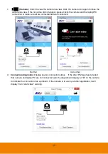
Page 17: ...nection to make sure all are corrected and well connected Normal Un normal d Connection diagnostic Display devices connection status If the AVer PTZApp has detected that camera and laptop PC are not connected well the diagram will display an X on the camera to indicate the connection has a problem If the camera is in use by another application it will display Can t start video warning ...

Page 18: ...e CAM520 camera s firmware 1 Click Update Now 2 A dialog will display the current firmware version and available new firmware version internet connection is required 3 To auto update click Auto Update and update process will start The new firmware will be downloaded first then the new firmware will be uploaded to camera Note Please make sure camera power and laptop PC are all well connected and st...

Page 19: ...ooting collect more system information for troubleshooting before you contact AVer technical support h Currently selected device This field displays currently selected VC or CAM device controlled by PTZApp If you have more than one AVer VC or CAM devices connected to this PC Mac PTZApp is running you can click on the drop down list to select other AVer VC or CAM device ...

Page 20: ...16 Select Remote Controller CAM520 supports two different remote controls Please select your remote ...

Page 21: ...mote control 1 If PTZApp detects computer connects to multiple VC CAM you can select which camera you like to control through the dropdown list 2 Next Click Change Binding button 3 Select which camera number of remote control it maps to 4 Click Save to save settings To un save the settings click Abort 1 2 3 ...

Page 22: ...18 Hotkey Control Enable hotkey control to use keyboard control camera s movement and backlight 1 Select Settings 2 Set Hotkey Control to On 3 A hotkey description as below figure shown 1 2 ...

Reviews: