


Page|10
www.avenview.com
IR IN
HDMI 1
DMI
H
2
SERVICE 2
COAX
AUDIO
AUDIO
AUDIO 7
AUDIO 1
AUDIO 2
AUDIO 3
AUDIO 4
HDMI
BYPASS
CAT5e/6/7
CAT5e/6/7
CAT5e/6/7
PC
HDMI 1
HDMI 2
3
DMI
H
4
5
6
7
INPUT
R
L
CV
8
LAN
RS-232
DC 24 V
OUTPUT
IR OUT
SERVICE 1
ON OFF
DSP PROG.
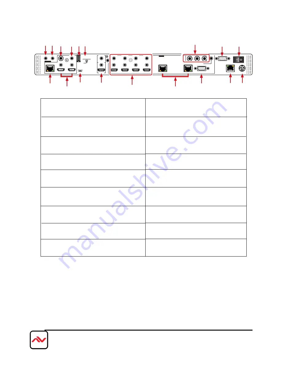
1.
IR OUT:
Connect to the supplied IR Blaster cable for
IR signal transmission. Place the IR Blaster in direct line-
of-sight of the device to be controlled.
2.
IR IN:
Connect to the supplied IR Extender cable
for IR signal reception. Remote should be in direct
line-of-sight of the IR Extender.
3.
OUTPUT CAT5e/6/7:
Connect to the Receiver unit
with a Single CAT5e/6/7 cable for transmission of all
data signals.
4.
OUTPUT HDMI:
Connect to a HDMI equipped
TV/monitor for display of the HDMI input source
signal.
5.
OUTPUT COAX:
Connect to audio sound equipment
such as speaker or amplifier for audio sound output.
6.
OUTPUT AUDIO:
Connect to peaker or
amplifier for audio sound output.
7.
SERVICE 1 & 2:
Reserved for firmware update use
only.
4.2
I
NPUT PANEL (SC-HBT-HDMA-8X4)
Rear
Panel
4
10
11
13
1 2
5
6
IR OUT
7 8
14
16
12
15
17
7
9
3
9.
BYPASS:
Connect to a HDMI equipped TV/monitor
with audio device for both video and audio output
display.
10.
INPUT HDMI 1-4 & AUDIO 1-4:
Connect to
HDMI/DVI source
11.
INPUT CAT5e/6/7:
Connect this port to CAT5e/6/7
Transmitter with CAT5e/6/7 cable to extend the
signal up to 100m.
12.
INPUT PC & AUDIO:
Connect this port to PC/
Laptop with audio signal for input signal selecting.
13.
INPUT CV:
Connect this port to source such as
video player or Set-Top-Box for input signal selecting.
14.
RS-232:
Connect from PC/Laptop for RS-232
command sending to control the device.
15.
LAN:
Connect from PC/Laptop with active internet
service for Web GUI control with RJ-45 terminated
cable.
16.
POWER TOGGLE:
Powers the device On and
OFF
8.
DISPLAY PROG. SWITCH:
Reserved for
firmware update use only. Default setting is on OFF.
17.
DC 24V:
Connect the adaptor with power cord
included in the package and connect to AC wall
outlet for power supply.


