background image

www.avenview.com 


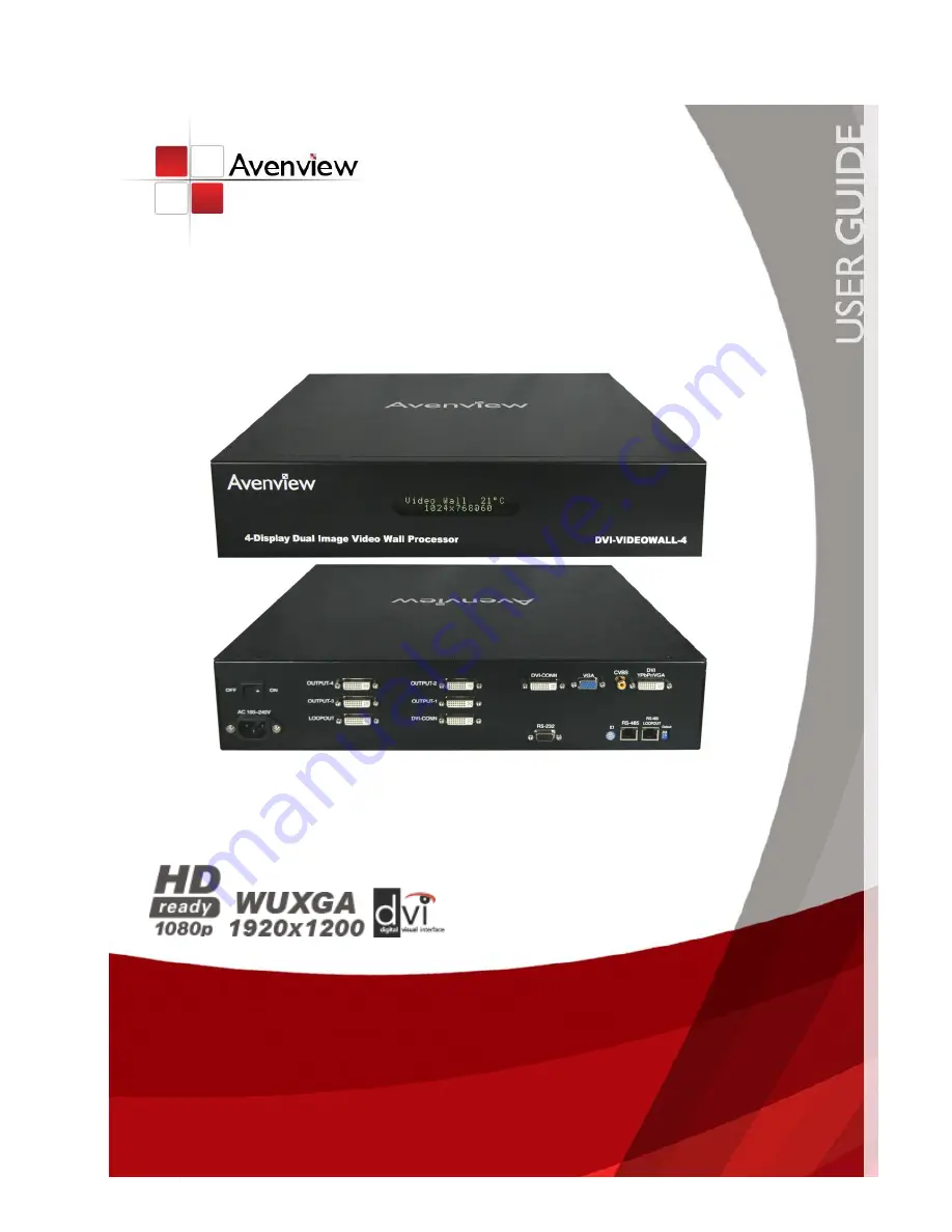
4 Display Video Wall Process


Model #: DVI-VIDEOWALL-4 


© 2009 Avenview Inc. All rights reserved

.   

The contents of this document are provided in connection with Avenview Inc. (“Avenview”) products. Avenview makes no representations or warranties with 
respect to the accuracy or completeness of the contents of this publication and reserves the right to make changes to specifications and product descriptions at any 
time without notice. No license, whether express, implied, or otherwise, to any intellectual property rights is granted by this publication. Except as set forth in 
Avenview Standard Terms and Conditions of Sale, Avenview assumes no liability whatsoever, and disclaims any express or implied warranty, relating to its products 
including, but not limited to, the implied warranty of merchantability, fitness for a particular purpose, or infringement of any intellectual property right. 
Reproduction of this manual, or parts thereof,


in any form, without the express written permission of Avenview Inc. is strictly prohibited.                                                                                                                                                                                                                                                                                                                                 


Summary of Contents for DVI-VIDEOWALL-4

Page 1: ... at any time without notice No license whether express implied or otherwise to any intellectual property rights is granted by this publication Except as set forth in Avenview Standard Terms and Conditions of Sale Avenview assumes no liability whatsoever and disclaims any express or implied warranty relating to its products including but not limited to the implied warranty of merchantability fitnes...

Page 2: ...nd Outputs 7 1 6 2 I O Connectors 8 1 7 Before Installation 8 Section 2 Installation 9 2 1 Software Installation and Setup 10 2 1 1 System Requirements 10 2 1 2 Software Connection 10 2 1 3 Software Operation 12 2 2 Cascading Multiple Devices 23 Section 3 Specifications and Supported Resolutions 24 3 1 Specifications 24 3 2 Supported Resolutions 25 3 2 1 DVI IN 25 3 2 2 VGA 25 3 2 3 DVI OUT 26 Sec...

Page 3: ...ns The Avenview DVI VIDEOWALL 4 4 Display Video Wall Processor has been tested for conformance to safety regulations and requirements and has been certified for international use However like all electronic equipment s the DVI VIDEOWALL 4 should be used with care Read the following safety instructions to protect yourself from possible injury and to minimize the risk of damage to the unit Do not di...

Page 4: ... sizes you want for viewing The embedded scalar converts signals from input sources to match the native resolution of monitors flat panel displays projectors as well as user selectable output settings up to WUXGA 1920x1200 The DVI VIDEOWALL 4 sends the resulting mixed video thru DVI interface to the connected monitors projectors based on the display layout The layout can be readily modified to fit...

Page 5: ...www avenview com 5 ...
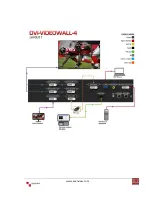
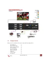
Page 6: ...stallation of the converter please check the package contents DVI VIDEOWALL 4 x 1 DVI to DVI VGA Y Cable x 1 VGA to Component Adapter x 1 DVI to VGA Adapter x 1 30cm DVI to DVI Cable x 1 RS232 to USB Adapter x 1 Software CD x 1 AC Power Supply x 1 User s Manual x 1 ...

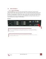
Page 7: ...and then the DVI VIDEOWALL 4 will display two of them simultaneously on the same screen Figure 2 shows the rear panel connectors for the video inputs of a DVI VIDEOWALL 4 and Table 1 illustrates how you can connect video devices and display to DVI VIDEOWALL 4 Rear Panel To reset the DVI VIDEOWALL 4 to factory default settings Turn on the DVI VIDEOWALL 4 then switch both DIP Switches simultaneously...

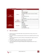
Page 8: ...play DVI to DVI VGA Y Cable 1 7 Before Installation Put the product in an even and stable location If the product falls down or drops it may cause an injury or malfunction Don t place the product in too high temperature over 50 C too low temperature under 0 C or high humidity Use the AC power adapter with correct specifications If inappropriate power supply is used then it may cause a fire Do not ...

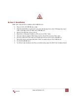
Page 9: ...4 3 Plug in DVI to DVI VGA Y cable to DVI IN 4 Plug in VGA to Component Adapter to VGA connector of the Y cable 5 Connect a device equipped with DVI output such as PC to DVI connector of the Y cable 6 Connect a device with VGA output such as laptop to VGA connector of DVI VIDEOWALL 4 7 Connected a device with Composite video output to composite input of DVI VIDEOWALL 4 8 Turn ON DVI VIDEOWALL 4 9 ...

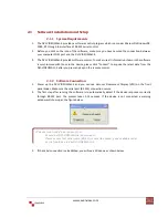
Page 10: ...the DVI VIDEOWALL 4 after you press any key on the remote control 2 1 2 Software Connection 1 Power up the DVI VIDEOWALL 4 and you can see Vacuum Fluorescent Display VFD on the front panel blinks Make sure the serial port RS 232 connection secure 2 The first step after running the software is to automatically detect if the device responses correctly through RS 232 port The process takes 5 15 secon...

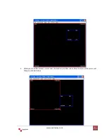
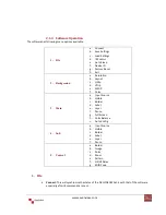
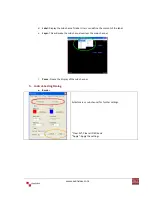
Page 11: ...www avenview com 11 4 While you move the mouse s cursor near the borders in either red or blue the icon of the cursor will change as shown below ...

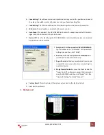
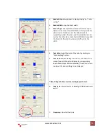
Page 12: ...on b Layout c HFlip d VFlip e SWAP f Color 3 Main a Input Source b Visible c Border d Label e Layer f Pause g Full Screen h Color Balance i Auto Config 4 Sub a Input Source b Visible c Border d Label e Layer f Pause 5 Control a Border b Image c Color d Zoom e Pattern f HS VS Delay g EDID Code 1 File a Connect This will synchronize the status of the DVI VIDEOWALL 4 with that of the software especia...

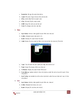
Page 13: ...the DVI VIDEOWALL 4 while multiple devices are cascaded by RS 232 over CAT5 module 1 Assign an ID for the connected DVI VIDEOWALL 4 type a number in the ID Number of the device ID setting area and then click Write 2 Read the ID of the connected DVI VIDEOWALL 4 click Read and the ID will show up 3 Super Control all devices cascaded will receive and respond the same way when you are operating the co...

Page 14: ...hannel s border d Label Display the main channel s label Users can define the content of the label e Layer This will make the main channel overlays the sub channel f Pause Freeze the display of the main channel g Full Screen Display the main channel full screen h Color Balance Automatically do the color balance while the main channel s input is from VGA YPbPr i Auto Config Automatically do the aut...

Page 15: ...ne the content of the label e Layer This will make the sub channel overlays the main channel f Pause Freeze the display of the sub channel 5 Control Setting Dialog a Border Select main or sub channel for further settings Clear All Clear all OSD items Apply Apply the settings ...

Page 16: ...the other video input Option Middle simply adds the border half inside the video and half outside the video 4 Text Color Select the color of the label by clicking on Color Setting button 5 Text Auto While selecting Text Auto the label on the screen for each channel will display its corresponding input channel type While unselecting Text Auto users can input the desired string to be displayed Only ...

Page 17: ...www avenview com 17 b Image 1 Choose the scaling type for the main channel at full screen display 2 While Blend is selected users can use the slider to control the degree of blending c Color ...

Page 18: ... com 18 1 Select the main or sub channels 2 Reset Restore all the setting on this page back to their default values d Zoom 1 Select the main or sub channel 2 Default Restore the selected channel without zoom effect ...

Page 19: ... output will display the selected pattern While unselecting this item the output display works normally 2 The orange border indicates which pattern is currently selected Users can choose one of the provided patterns by moving cursor and clicking at the desired one 3 Define the pattern s color by clicking at the rectangle inside the ellipse and then use the sliders for choosing R G B depths ...

Page 20: ...g EDID Code 1 Save Save the read back EDID Content in PC 2 Setting Automatically setup the output resolution according to the content of EDID This setting is according to the content of EDID and the optimum resolution for the monitor might be different because of the limited information of the acquired EDID info ...

Page 21: ...www avenview com 21 Control Display Layout Users can define the resolution of the output video to displays X Total Y Total ...

Page 22: ...y default is quad view as shown To activate the new settings for each display please click the Window x button under Update Parameters section on the left of the control interface Enable All Disable All Default Layout Clicking on Disable all button will make all the connected monitors have an identical display i e the output from the front end mixer Default Layout will replace the current display ...

Page 23: ...Multiple Devices The DVI VIDEOWALL 4 has a dual view processor which allows you to see 2 videos on the same screen When you add an additional DVI VIDEOWALL 4 or DVI VIDEOWALL 9 you can get additional 4 or 9 video outputs For example 2 devices of DVI VIDEOWALL 4 cascaded can provide 8 video outputs displayed simultaneously on the connected displays ...

Page 24: ...Cascade Yes up to 255 units Input TMDS Signal 1 2 Volts peak peak ESD Protection Human body model 15kV air gap discharge 8kV contact discharge Input 2 x VGA 1 x DVI 1 x Component 1 x Composite 1 x RS232 1 x RS485 Output 5 x DVI 4 x VGA DVI Connector Type DVI I 29 Pin female digital only VGA Connector Type HD 15 15 pin D sub female RS232 Connector DE 9 9 pin D sub female RCA Connector 75Ω RJ45 Conn...

Page 25: ...Hz MAC 640x480 67Hz VESA 640x480 72Hz VESA 640x480 75Hz VESA 640x480 85Hz VESA 800x600 56Hz VESA 800x600 60Hz VESA 800x600 72Hz VESA 800x600 75Hz VESA 800x600 85Hz Supported Mode Resolution MAC 832x624 75Hz VESA 1024x768 60Hz MAC 1024x768 60Hz VESA 1024x768 70Hz IBM 1024x768 72Hz VESA 1024x768 75Hz MAC 1024x768 75Hz VESA 1024x768 85Hz VESA 1152x864 75Hz MAC 1152x870 75Hz SUN 1152x900 66Hz SUN 1152...

Page 26: ...0 60Hz HDTV 1080p 1920x1080 60Hz VESA 640x480 60Hz VESA 800x600 60Hz VESA 1024x768 60Hz VESA 1152x864 75Hz VESA 1280x1024 60Hz VESA 1280x1024 50Hz VESA 1280x768 60Hz VESA 1366x768 60Hz VESA 1400x1050 60Hz VESA 1400x1050 50Hz VESA 1152x864 75Hz VESA 1600x1200 60Hz VESA 1920x1200 50Hz VESA 1920x1200 60Hz ...

Page 27: ... and displays Configure the output video resolution so that it doesn t excess the native resolution of the display in this case the message of out of range is usually showed on your screen Poor Quality We suggest that don t use T connectors to split your video source into to images displayed on two different screens That will lower output video quality Use a distribution amplifier instead of T con...

Page 28: ... A solid UTP CAT5e cable shows longer transmission length than stranded STP CAT6 cable For long extension users solid LAN cables are your only choice 4 EIA TIA 568 B termination T568B for LAN cables is recommended for better performance 5 To reduce the interference among the unshielded twisted pairs of wires in LAN cable you can use shielded LAN cables to improve EMI problems which is worsen in lo...

Page 29: ...patory profits or for punitive incidental or consequential damages in connection with the furnishing performance or use of the Avenview hardware software or other products and documentation provided herein Avenview Inc reserves the right to make changes without further notice to a product or system described herein to improve reliability function or design With respect to Avenview products which t...

Reviews: